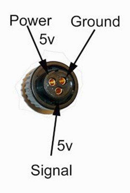
I have the RC8 board and when I connect what should be the power and ground pins, it starts to short the 5V connection. If I reverse the signal and 5V connection it works fine but as soon as I connect to the module the Flowmeter starts to show product leaving. But I do t physically have the pump on. I followed the pinout according to the diagram I thought. Do I just have it wired backwards or do I have a bad Flowmeter
That’s the one!
Since I posted that yesterday afternoon, I have verified that the connection is correct. So Im not sure why the flowmeter is reading this way but I suspect I have my pins incorrect. I know the cytron can draw up to 13A but I was being cautious. I have 5 amp fuse installed, but think I should go up to a 10Amp
When I touch the footswitch nothing happens.
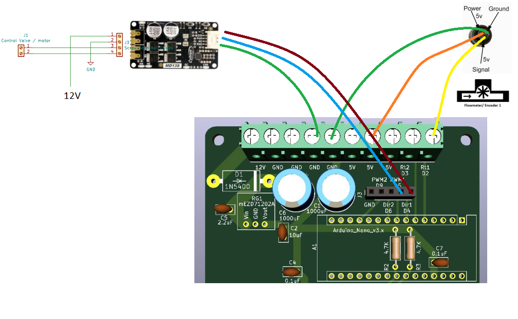
here is how I have the hoard hooked up.
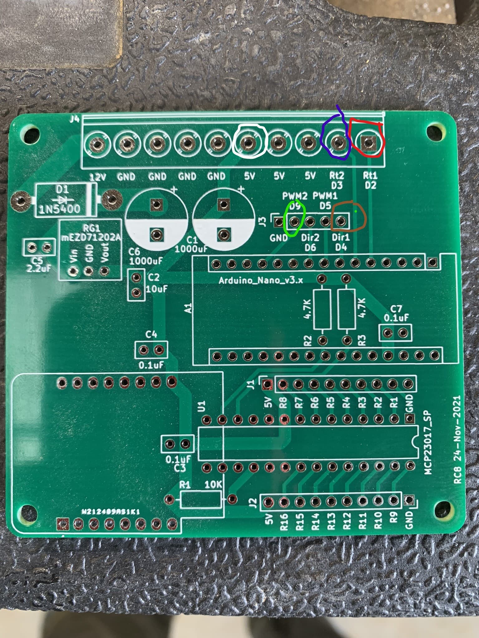
W8hite- Flowmeter power
Blue - Work switc8h/footpedal.
Red - Flowmeter si7gnal
Brown - Cytron Dir
green - Cyrton pwm

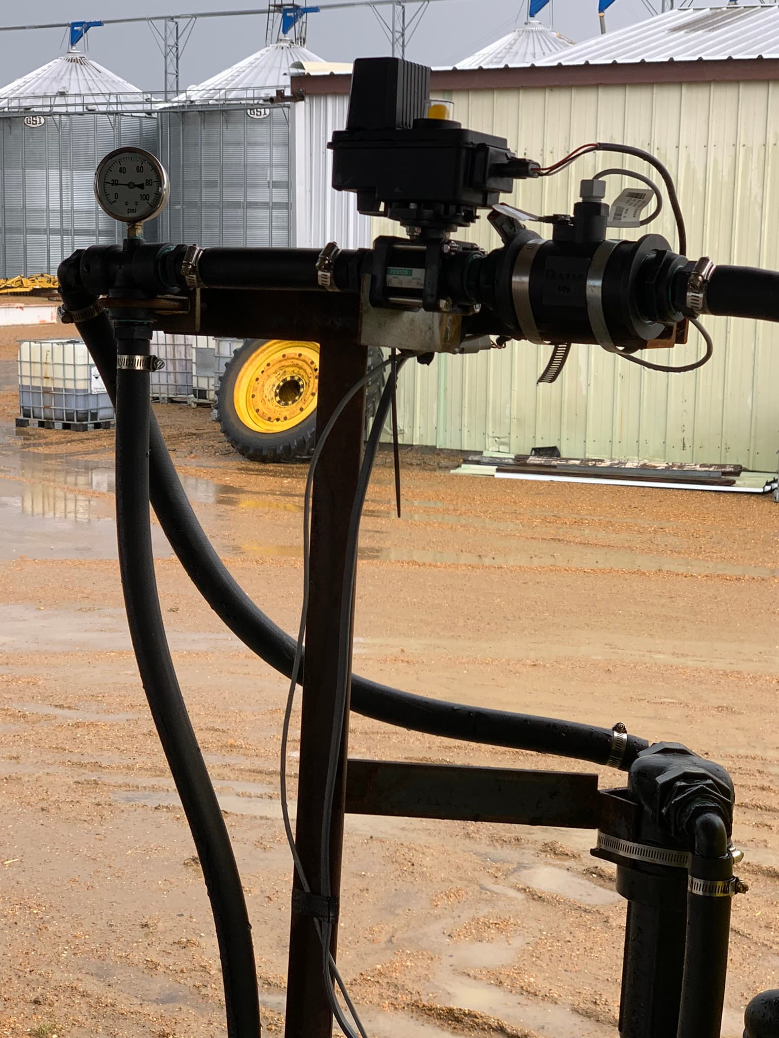
The pump I’m using
206-PWM_Product_Sheets.pdf (1.1 MB)
Yep,
It’s worthwhile knowing how the cytrons work compared to some other motor controllers.
Instead of a PWM signal for each direction of rotation, they take only a one PWM signal and then use a direction pin to reverse the polarity of the motor signal and hence change the direction of rotation.
The dir is just a hi/lo input and can be hard wired to 5V in an application where you want to change the e rotation direction permanently.
The RC board has a PWM1 and Dir1, to be used as a pair to control one cytron. And PWM2 Dir 2 for the control of a second cytron.
Easily confused and easy to think Dir1 could be for left and Dir2 could be for right for example.
Anyhow, rewire it and let us know how you go.
Please keep posting as you get this working. I’m keenly watching, as i am also doing the same setup as you. Just a few weeks behind.
I will keep you updated as I make progress. I have made the correction to my board to get direction, pwm and rate on the same module (0). I will be attempting a test this afternoon.

The flowmeter is now showing me what appears to be correct data when on (2.9-3.4 GPM about right for an ACE 206 pump. However when I turn the solenoid valve off it still shows a constant ~1UPM flow. Is this due to no calibration?
When I attempt to calibrate the module, I have my bypass closed, and I start at about 20psi. I hit the power button on and let it calibrate. After about 2-3 minutes the pressure has moved to almost 80 psi, it never locks the rpm I just end up stopping before I destroy the pump.
I have the valve set as standard. When I do get this calibrated will I still need to start and stop product with the physical switch? Or should I expect to be able to stop the flow with the master? Do I have something set wrong?

What is the expected UPM? What is the sprayer width, speed and application rate/acre?
The master switch will shut off the section relays and set the pwm to 0.
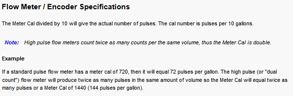
Maybe this also applies? If it says 1425 on the tag you would have to enter 142 as the sensor counts/unit.
I bet it does. I have made the change accordingly but the result is the same. When I attempt to calibrate it never locks, and goes to max pressure.
The master and section seem to have no effect on the valve, it runs either way when I open the physical valve. The flowmeter is also still showing constant flow even with the valve closed.
What is the expected UPM? What is the sprayer width, speed and application rate/acre?
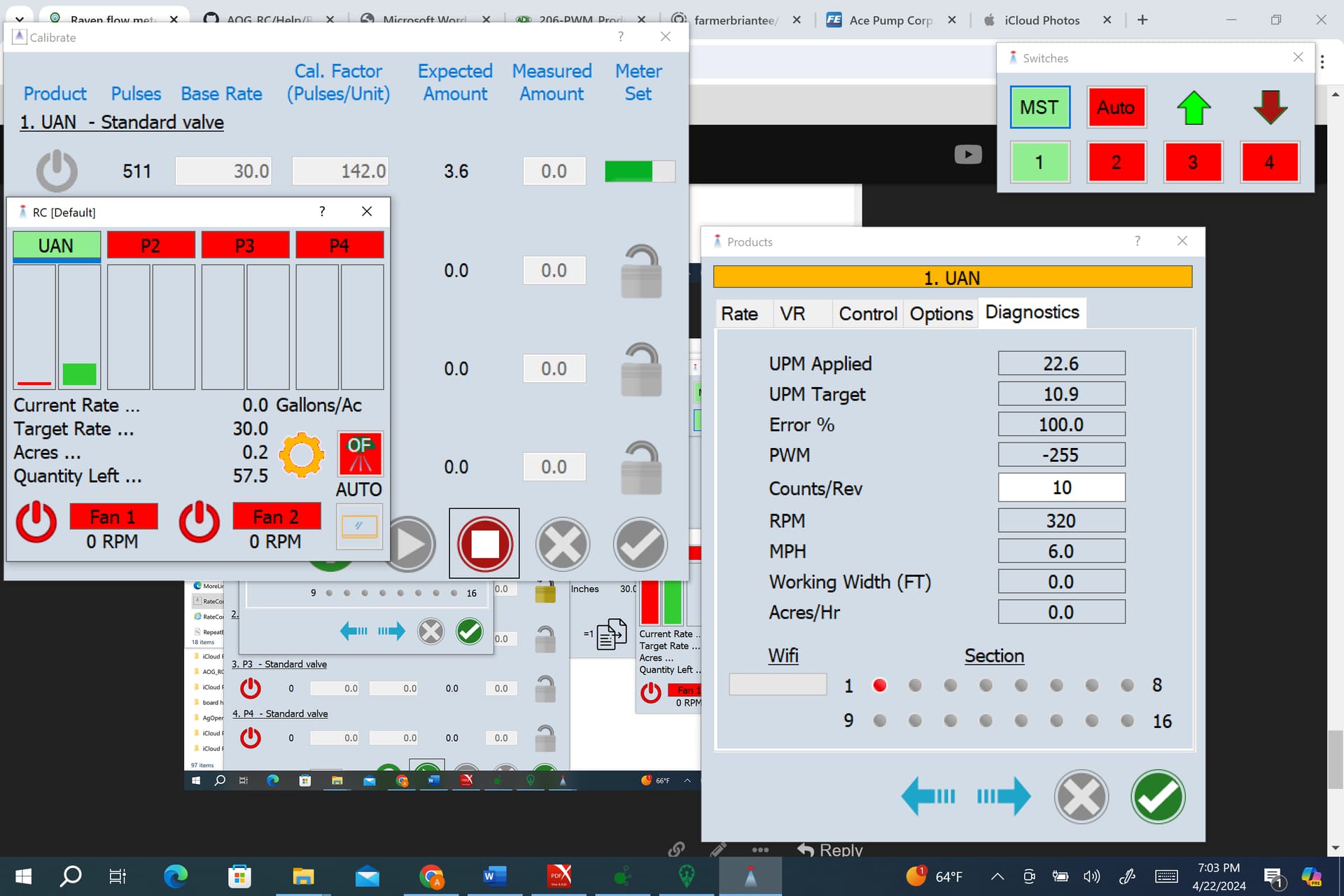
I want to apply 30 gal/ac. At 6mph, 30 foot working width, that should be just under 10 gal per min.
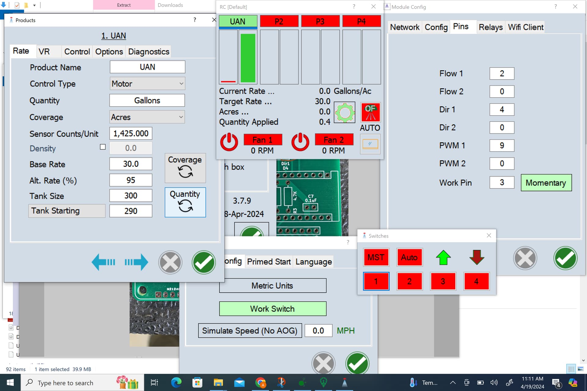
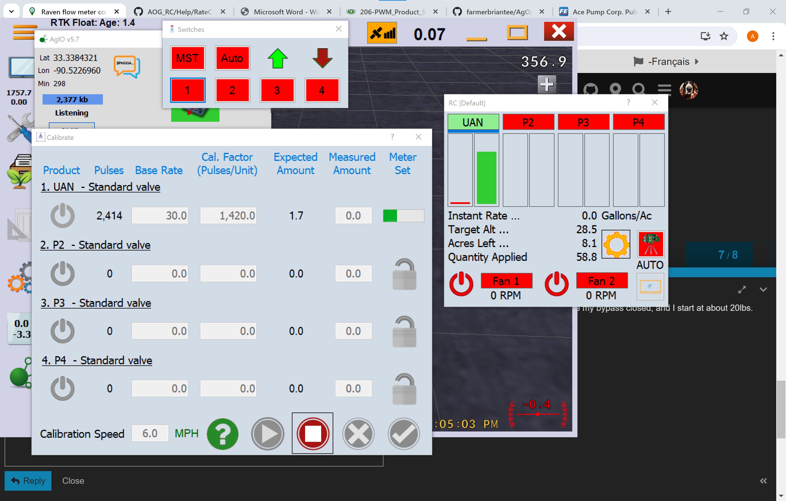
Here are my settings:
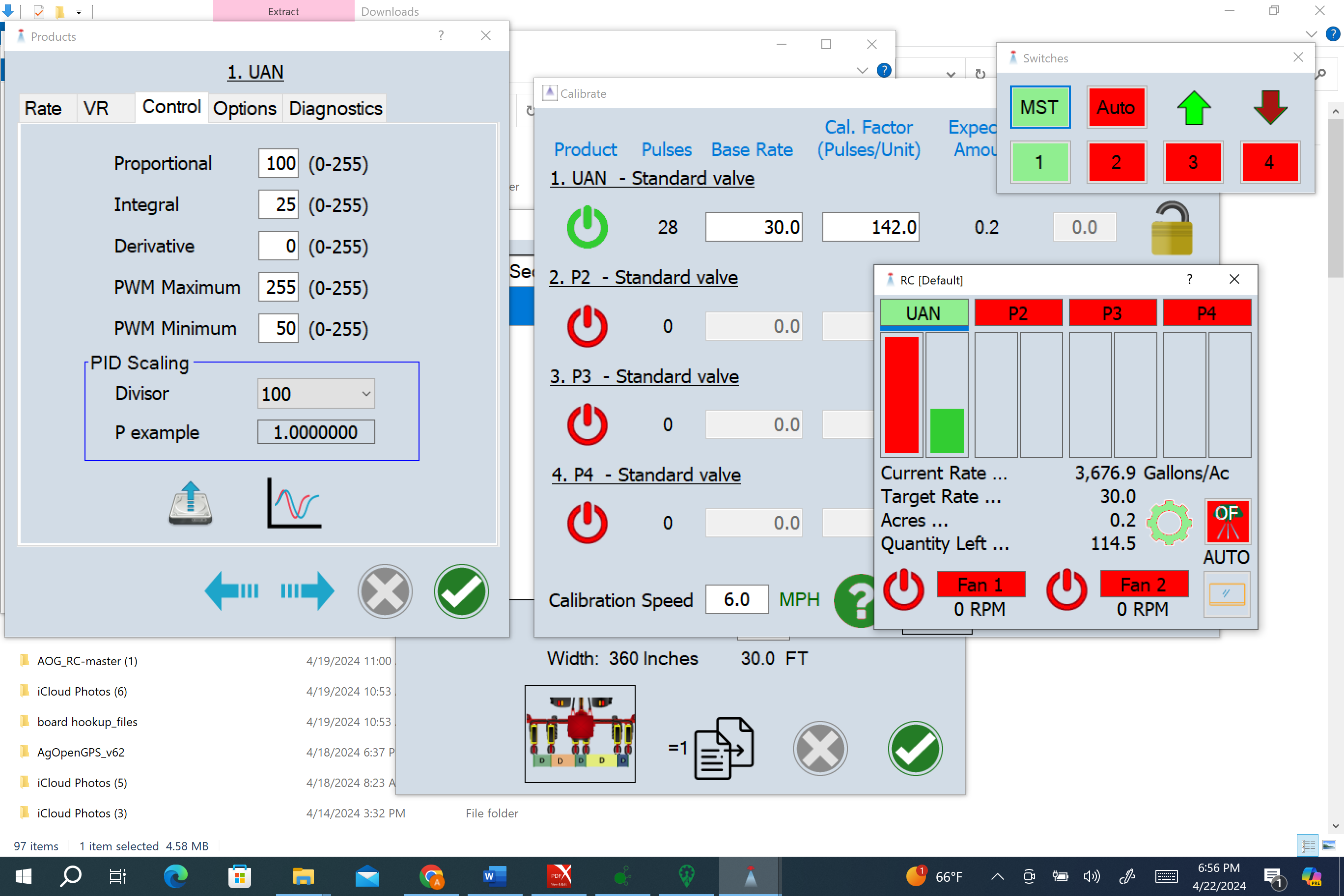
What it looks like when attempting to calibrate:
UPDATE:
I found this technical bulletin for the pump/valve! I’m not sure how much help it is though. I can seem to get the master to engage.
The master switch refuses to stay on, it turns on then off. also I get
I have tried running it as a combo close and a standard valve. The bulletin directs you to start with rate controller pwm at 100% before I can still not control the valve with the rate controller. There is no change when I power the hydraulics, with the master off, the pump just runs like normal. It does try to do something, I can see and hear a pressure change within the tractor and the spray line, I have ensured that the manual override was disengaged.
Does anybody know what I am doing wrong? I feel like whatever is not allowing the main switch to stay engaged is related to my lack of control. When I disconnect the harness from the valve it changes nothing, even though there were approximately 12v running to it.
Do you have a multimeter that reads HZ?
Time to check the flow meter is actually pulsing, and that the cytron is actually outputting a PWM to the valve.
Check your valve polarity is correct, as in it opens when it should, and closes when it should, not the other way around.
I can test Hz, what frequency range should I be looking for?
I didn’t realize that PWM solenoids were pole specific, I will try reversing the controller wires coming out of the Cytron
Your flow meter is pulsing 142 times per gallons? Get a rough idea of your gallons per second and then times it by 142. My multi meter has an auto range setting so it will just display the hz if I probe the output pin and ground on the flow meter.
You just need to make sure the hz are in the expected range. It could be that a resistor is required.
As for the pwm solenoid? Is it a solenoid or a butterfly valve that you have your cytron connected to?
Remind me again Are you varying the speed of the pump by controlling flow of oil, or controlling the flow of product to the boom?
Also, in the photo above what is the 3 wire valve after your flow meter? And how do you control that?
Great I will check this tomorrow, by output pin, do you mean the PWM pin on the Cytron from the board or the MA/MB from the Cytron to the valve?
Per my conversation today with the company that manufactures the above pump, it controls the flow of oil through the motor that is connected to the centrifugal pump. So I guess I really need to select “motor” instead of “standard valve” or “combo close” on the product menu?
The 3 wire valve is a TeeJet electric solenoid valve. It is wired independently, and is there to prevent product from leaking out when the system is off or when using it manually in cunjuction with a bypass.
By output pin I mean the wire from the flow meter where you expect the pulse to come from.
You shouldn’t change the setting to motor. Although a motor is controlling your pump, a valve is ultimately controlling the motor. The cytron closes and opens this valve multiple times per second to modulate the flow of oil and subsequently the speed of the hydraulic motor and ultimately the speed of the pump and flow of UAN.
Be sure the teejet value is open when you are running your tests and calibration. And that your bypass is closed too I assume.
I’d be really careful with the raven flowmeter wiring. Here’s what I went through few years ago.
I’m glad I didn’t make that mistake, its very easy to do based on some of the imagery out there. I did discover that if signal and power are reversed it will cause the entire board to malfunction.
Could that have caused a short? When I attempt to use my Hz function on my multimeter, per @Hman 's advice I get no reading. But I get 350mV when the board is powered with no flow and ~2.6-2.7V when flowing, does this mean it is outside my meters range? I can read 3 phase electric motor framerates with it… It is a Klein Tools CL700.