My idea of a “pass through box” looks something like this. The big cable with big 39 pin rectangle monitor connector, it’s just a common DB37 on the sprayer end.
This could be a very simple PCB that inserts between the sprayer PCB and conveyor cable. Most of the signals can pass straight through, and we could have the motor connections broken out to screw terminals or solder pads. Simple to install and simple to remove, no permanent modifications.
The sprayer control cabinet is sealed/watertight, has room for extra circuits, has 12v available, and has room for extra cable pass throughs.
I thought it would be ideal to put the relays in that control cabinet and then just run Ethernet/wifi to the tractor.
As a special bonus: the hydraulic controls are very similar, perfect place to tie a homemade auto boom height system into the sprayer.
1 Like
I’d love to hear more about your boom height! Thanks
I think I understand.
The problem is that the rate controller doesn’t now that the booms are being switched down line. The rate controller, by default, only tried to regulate when a boom section is on. So if you have your controller toggles on, then the rate controller always works, even when you change gears to turn at a headland. And if you have your controller toggle as off, then there is no regulation. Neither is ideal.
Not mentioned in the Cerea thread, but I believe there is a setting in the monitor that allows the system to always regulate even when all switches are off. That has the same negative as above - the system will regulate when you switch gears to turn around (and will then have a low application rate for a few seconds when you switch gear again and start spraying).
The Cerea author has connected to the spray monitor’s foot pedal switch to tell the system when all sections are off. For me that’s not ideal because I really want the relays out of the cabin.
I will think more on how to defeat this, but I’m not sure it’s possible without the foot pedal switch or de-coding the JobCom protocol.
Just ideas floating around in my head. I’ve strapped some ultrasonic sensors to the boom before and played with filtering the data and having a distance readout, but never any further.
I wasn’t quite able to understand through the translation how the db15 foot pedal connector worked, so I did my own test.
Shorting pins 1 (+12v sensor) and 10 (area switch) with the display menu E8.5.1 set to “high/low level” will turn all sections off. It doesn’t just turn off area, or also turns the sections off.
So you can add your section relays as normal; inline to the motors. Then an extra relay could be wired to db15. You come into a sprayed area and sections turn off one by one. Once they are all off, db15 relay turns on and all the individual section relays need to invert states as well.
Hello,
This week I had bought newer Hardi sprayer.
It’s Hardi Master Plus with HC5500 and Jobcom.
I have Trimble GFX-750 and Field-IQ module from old Hardi sprayer.
I also have AgOpenGPS setup.
Now I’d like to go to have section control on the new sprayer.
The easiest way is to buy Trimble cable to connect HC5500 by RS232 and controll it by serial connection.
Cable cost is about 200USD, but the license is over 1k USD. Which is extremally crazy for me - when today everything is contorled by isobus
Do You have any solution how to remove Jobcom from the sprayer?
My sprayer is mounted on tractor so Jobcom only handle section control. Is there any connection from Jobcom to hydraulics?
Maybe it’s easy task to get rid of Hardi electronics and go with Trimble Field-IQ module and application? I have everything unmounted from old sprayer.
What should I do?
1 Like
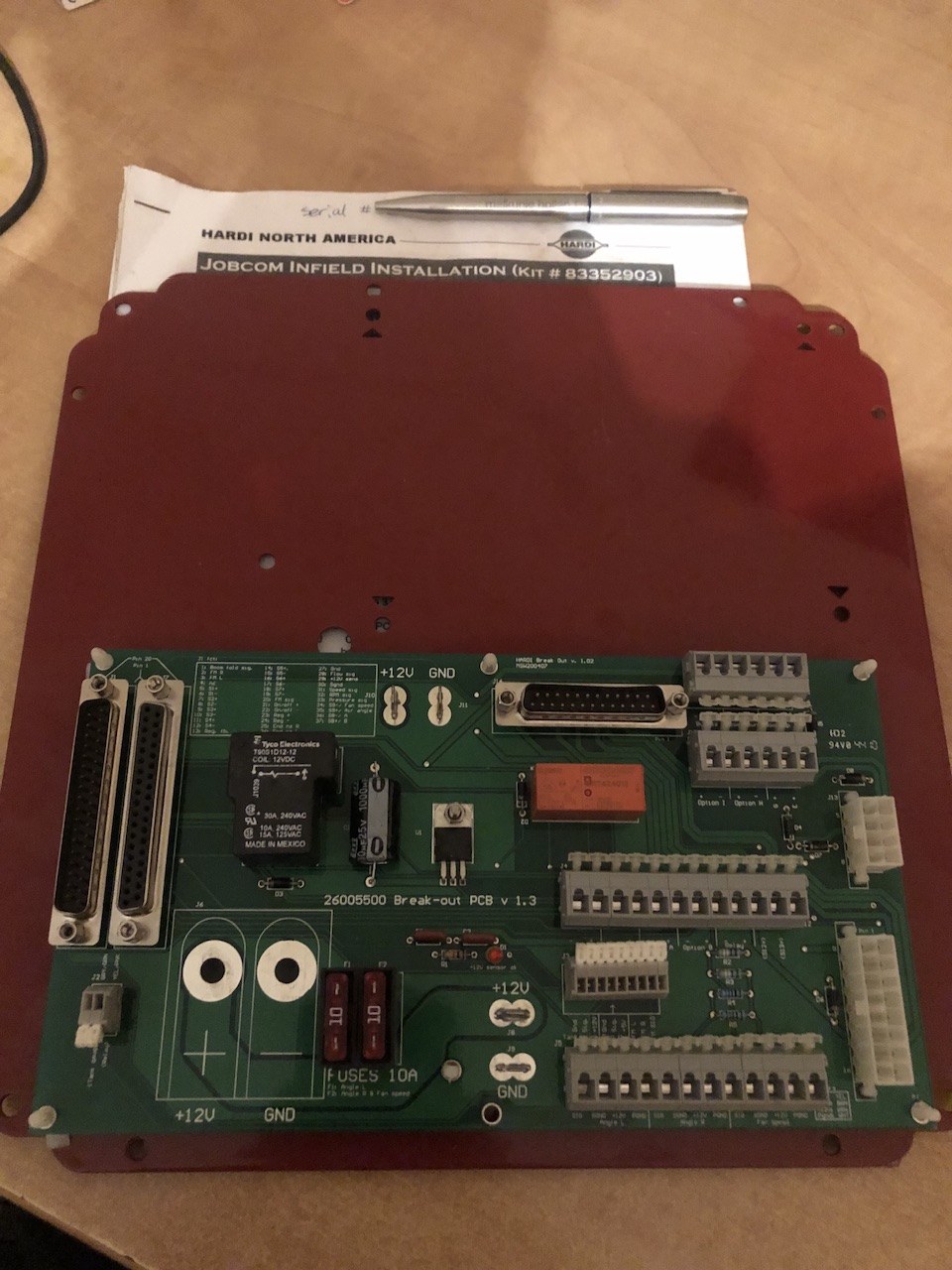
My sprayer has an electronics box that holds the Jobcom circuit board. It’s pictured in one the posts above. The Jobcom circuit board has many surface mount components.
I installed the Jobcom circuit board myself in order to use section control with Trimble. I recently remembered that fact. I still have the original circuit board that came with the sprayer. This board is much smaller and simpler. Here’s a picture.
There’s a db37 connector for the cable for the monitor. There’s a db37 connector that goes to the breakout box at the rear of the sprayer. There’s a whole bunch of break out points that I don’t need, I only need the flow meter and regulator connections (I don’t have a fan, tank level sensor, foamer, fence nozzles, etc). The relays seem to be for some options that I don’t have. The 5v regulator seems to be for the flow meter.
I’m thinking about reverse engineering the important parts of this simple board and then making my own circuit board to replace it. The new circuit board would have relays or motor drivers to switch the valves. The new board would read the status of the toggle switches in the cab. I’d probably use an ESP32 and add Ethernet to it. All the rate control stuff would pass through and work like normal through the Hardi controller.
This is about my 18th time starting this Hardi section project. A different approach each time. Who knows how much I’ll get done before getting side tracked this time around.
Thanks for your detailed info.
Do you remember if jobcom also do some communication with hydraulics? Or it’s only for “liquid side”?
I’m considering to remove IT and use just trimble Field IQ module and harness which I already have from previous sprayer
I do not know for sure, but I believe the hydraulics are completely separated.
There are pins labelled Tilt, but I think they are actually for fence row nozzles. There’s a pin labelled fold, but I’m not sure what it’s for and I don’t think it does anything.
do You remember if seria connection provide “speed” data from GPS or do I need to prepare cable for speed sensor?
I believe with my serial connection between the cfx750 and HC5500 that I was able to switch between GPS speed and wheel speed somehow.
do You have this setup still running?
I just ordered cable and license, so in few days I need to set up a setting.
What should be set on HC5500 side and what on GFX-750?
If your not using rate control it’s quite simple as job com doesn’t need ti be in the loop but with rate control job on needs to know which sections are active
I uploaded one of my works from the past years to YouTube, I think it was 2015, I used a pepperl-fusch ultrasonic sensor, 3m. It was a sensor with a working distance and working with 4-20 mA, I got very good results, and my valves were on-off valves, so there was no proportional control. The height distance could be adjusted in an Arduino code, for example from 40cm to 100cm, but I did not try it in the field. I think the company that does this job best is Norac, because they use proportional valves, and they also offer the option of soil or plant distance on the control screen.
1 Like
I still have all the components but I have dismantled the setup because I do not have room in the cab for the Trimble monitor anymore.
My monitor is a CaseIH CFX750 which is a different (older) monitor than your Trimble GFX750. My monitor required a $750 VRA license, but I believe you are correct that the GFX750 requires a FieldIQ license.
On the Hardi HC5500 you will need to change menu 2.3 Serial/VRA to Enabled.
On the Trimble you will need to find the implement/FieldIQ menu and set it to HC5500. You’ll see other rate controllers like Bogballe and Amazone. From there you’ll hit next and have straight forward menus where you enter in boom measurements, number of valves, etc.
The Hardi switch box will allow to select valves between “off” and “auto.” I never found a good way to manually turn on sections. There wasa menu for it, but it didn’t work with the Hardi selected. I often changed menu 2.3 to disabled when necessary to manually override things.
Hopefully your GFX is better in this regard. At the very least, for your 3pt sprayer you don’t have to turn off your PTO pump to make very sharp backup turns into corners like I do with my trailer sprayer. When I forget to turn the PTO pump back on is when I had to manually override.
thanks,
I hope I will test it on Saturday.
Regards
Jacek
1 Like
Tested,
works fine on a farm, next I need to test it on the field
Is it possible that when my GFX-750 is off then I can enable and disable sections manually - just from HC5500?
It seems I do need to disable VRA/GPS option in menu.
I think you will get an alarm on the HC5500 for Serial VRA disconnected, but I think if you ok that then you can have manual control.