I want to contol my Rau sprayer by AOG. I found out how to switch sections on and off, but this is after the spraying computer. I think I get problems with pressure and applied fluid, because computer thinks sections are open (or closed) and in fact it is not.
So opened the spraying computer, a Rau telemat txae.
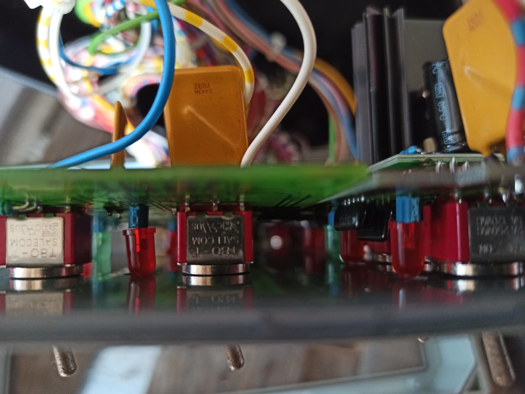
My knowledge of electrics are just basic, how should I connect to the section switches, these are salecom t80-t switches, 6 legs dpdt? I think. see picture.
Best would be if I could use manual switches and AOG, my question is how to connect relayboard to computer and the computer wil know if AOG switches sections? Is it possible?
Hello;
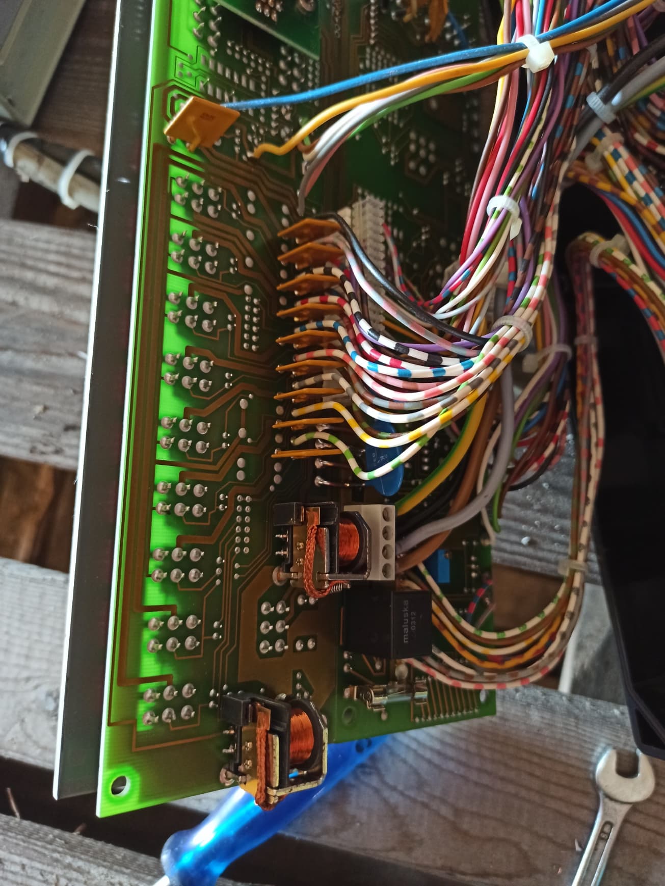
I think from the 90’s devices, I was using those colored wires in those years, and the screw heads are for flat screwdrivers.
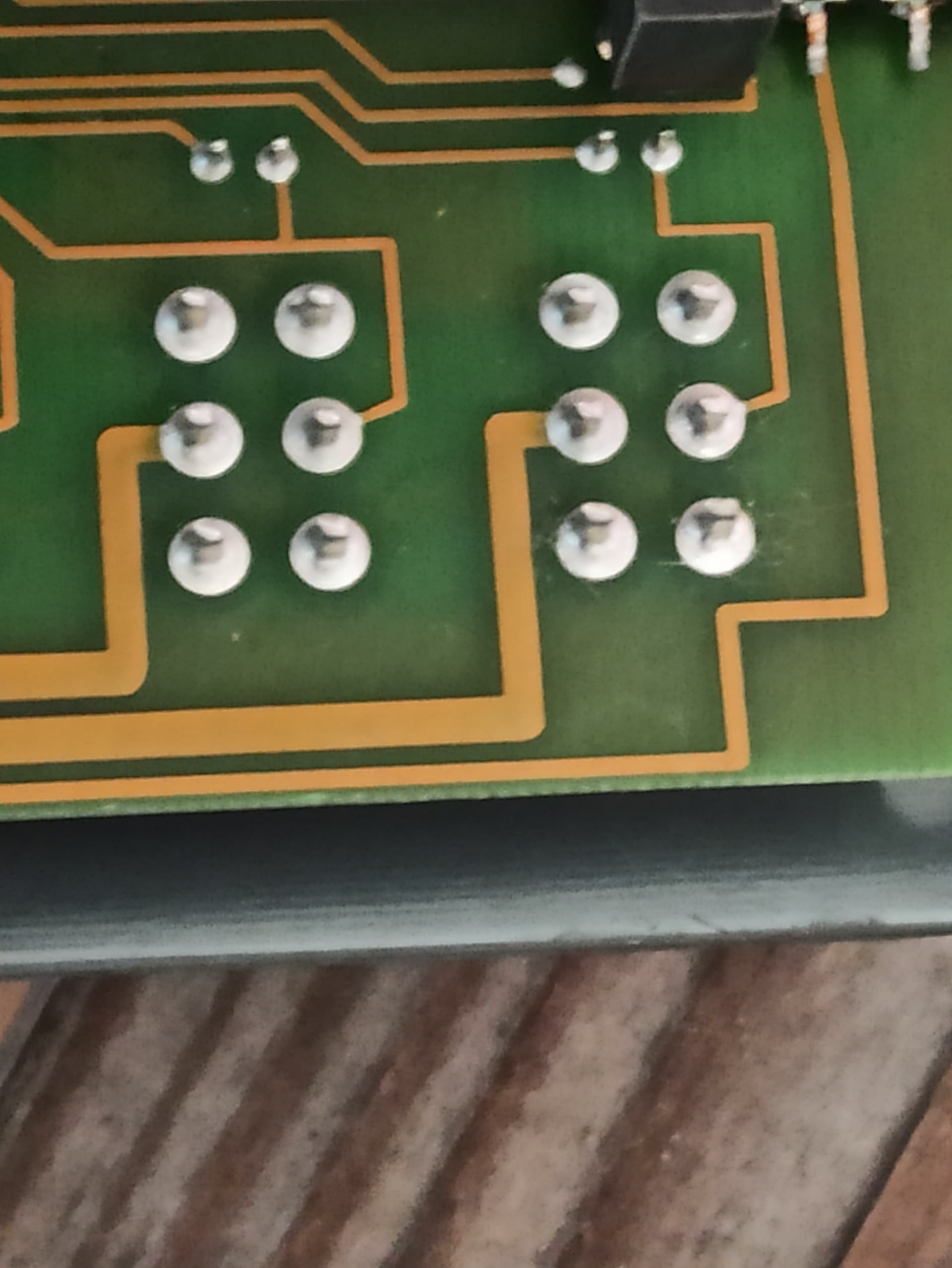
As far as I understand, the right side of the DPDT switch controls the valve (3 pins), while the left part sends the on-off information of the valve to the processor and controls the LED.
1- Are you going to connect the device in this photo to AOG?
2- Does each part of the device control an independent relay?
3- Does the device perform ratio control?
Yes, I want to use this device to connect to AOG if possible. But struggeling with switches. Each switch is going to a relay that triggers section. I can t-in aog to those relays but computer does not know if section is on or off. Then liters applied and pressure spraying will not be correct. So maybe I can connect on toggle switches?
The output signal from the relay will have to go to sprayer AND to the computer that manages rate control.
This is similar to want I’m working on on Mueller box: Mueller SprayControl section control - #6 by Gg1212
It has rate control. After reading these posts I see it is not that simple. I follow topics mentioned and keep thinking about how to make it. Keep you informed.
Haha that’s my video, happy to make an English version if that could help!
So as said, this is not finished yet and I’m still waiting for some parts from Ali.
Currently I’m using a PC817 optocoupleur board to read the section status I connected only the wire on which there is +12v when the section is open. On the other side of the board I connected GND and ESP32 pins so that when a section is open the ESP32 section pin is triggered (GND). Then there is a relay board connected to ESP32 and I use a 16 relays because it is reverse polarity so I need 2 relay for each section. The output of the relay is connected to sprayer.
Also I have done modification on MTZ section control code in order to reduce the code to only what I need and I have also added code to setup WiFi as a client to my phone hotspot and implemented communication to AOG for UDP working with v5.7.2
Still in progress: I need to send GND signal to tell the Müller rate computer the section is open. So I’m gonna put a second PC817 board after the relays to forward a GND signal to rate computer when a section is open. I don’t know how is the Spridomat but for Müller the rate computer can be separated from switches box, so I 3D printed a box which will be placed in between and will forward all the signal from switches box (flow sensor, speed, rate,…) except section signal that will be coming from second PC817 board based on the relay status. This is required for getting the right rate from computer when spraying in auto mode because the computer need to know relay status instead of switches.
Note that in order to set up all that you need to fully understand your sprayer computer, what signal goes where and when. So you can simulate that signal from the section control setup.
Thanks for your reply in Englisch! I am not good at electronics, but am learning by doing things. Like you mentioned I should understand my sprayer computer good to make it work. I will request a sceme from the dealer who sold it to me, hopefully he can help.
My sections are reverse polarity to, but in the sectionparts is a relay that switches polarity. by triggering an other relay to send GND to the sectionpart. The relay reverses polarity and open/close till microswitch is touched and circuit is broken. That was the easy part to figger out.
So I think when I can send signal of sections to the computer the rate applied will be good. I can instruct computer the rate to apply(l/ha, auto modus), let it calculate rate to apply (from speed) and pressure and the sections wil be opened/closed by AOG. That should work I guess.
This way I do not have to change anything for flow sensor.
Yes, so there should be wires used to send section status signal from telemat txae to the quantotron TX. You need to identify these wires and how is the signal sent in order to then simulate the signal from AOG controlled relays.
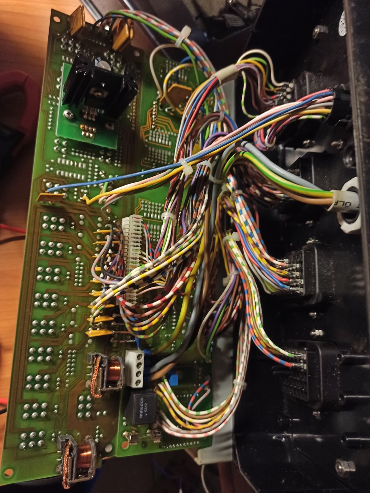
It is getting colder…time for my sprayer to make section control. As is said I had to identify cables for valves and cables for sending info to computer (quantotron TX) I succeded in doing this. when power (12v) is given to valves they are closed. signal to computer is zero.
I want my set-up like you, Gn1212, as you described in your github and video. My valves are not bi-polair so 8 relais will do, 7 sections. What relaisboard I need, NC I gues?
For reading the status of the manual switches I need an 8 channel optocoupler board, 7 sections and 1 for the main switch I think? And an extra optocoupler board to send signal to computer.
I assume not all your boards are in the black box you put between computer and control panel Gn1212?
I think it gets time to buy some hardware, think about how to connect all together en to make a box and cable where I can put everything in. Somebody any suggestions?
Yep all makes sense.
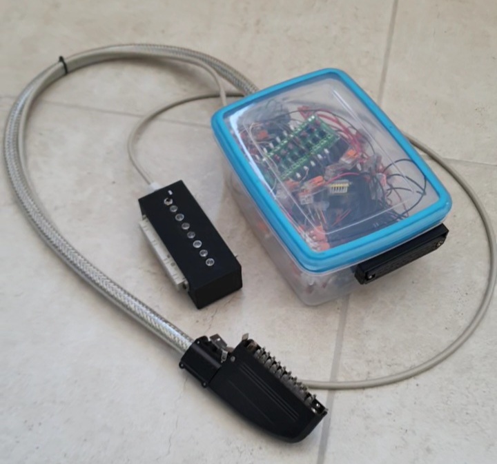
Unfortunately no, the black box only contains wires (box to box, section state from relays, powering leds, auto/man switch). All the boards are in another box that I put behind the driver seat but that’s not something very professional. It’s a food box in which I dropped everything and fixed the connectors.
I keep studying about this, like your setup very much and ordered parts (optocouplers, relay-board and ESP32. My switch board when unpowered all sections are open, no reversed polarity. Have to think how to implement this.
I’ll keep you informed, and if I am stuck I’ll drop a question.
Your solution with the food box is really low budget, your connector looks professional
Hello, I am implementing section control, ago already controls the switches in the computer, the main switch is on and the sections are turned off, ago gives a signal and the relays open the sections, I can also do it manually by lifting the button and turning on each section manually, but ago does not see it, or could you help me solve my problem? I have 5V on the buttons and they give a signal for opening and closing
sorry for my english, I use a translator