I have the 16-channel relay board connected by UDP (I used the wiring diagram for machine USB) can only get 3 relays to switch on and off. I have moved wires around and can’t get any more working. I also noticed in Brian YouTube video that he can test the relays in AGiO all 16 will switch from 0 to 1 when he hits the test button, mine will only switch the far right from 0 to 1.I have set up agopengps to use 12 switch’s and assigned pin 1 through 12 to switch 1 through 12. I must be missing a setting or something
1 Like
You must edit the machine.ino.
so set more pins for output.
Like this:
then end of the file more to edit:
After editing make new upload to you board.
And now you can select pins usage in AOG Machine setup.
3 Likes
Thanks have some learning to do
After doing this, everything works great but…
If I change the coverage % it seems to change into back to original and then only 3 of 12 sections work. Same thing happens when changing the on/ off delay. I am using version 5.7.1 working fine. Just have to remember to disconnect from network before changing.
I tried 5.7.2 with latest ino and had same results. Why would it need to write to INO when changing overlap. Is there a easy way to disable it writing to machine nano?
Thanks
Can you please spend a few more words on what you meant with “disconnect from network before changing”?
I’ve spent quite some time today on the hydraulic up/down function - and failed. AgOpen produces beep tones when hydraulics are supposed to be activated, but the two corresponding relays do not react at all. They are always on. Section control itself works and I think that my source code (based on latest .ino) should be ok.
I have to pull out cord to router/ Ethernet switch. (That’s what I mean disconnecting from network) before changing the coverage % or section on and off timing.
I think there is something going on there other than writing to ino code. @Brian is the best guy to answer what could be causing this behavior
In the end I could solve my problems, so maybe others find the explanations below useful. Screenshots/code are from AgOpenGPS 5.7.2 and Machine_UDP_v5_6.ino (in release 5.6.34). Example is for an 8-relays-board for 6 sections and hydraulic up/down.
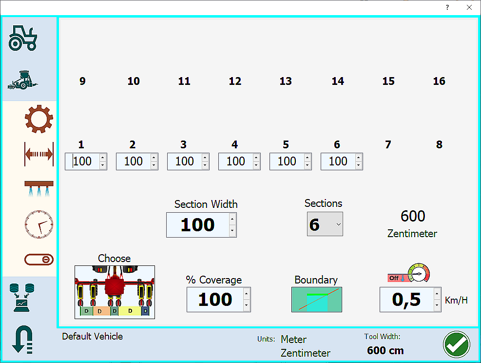
Set sections and section widths:
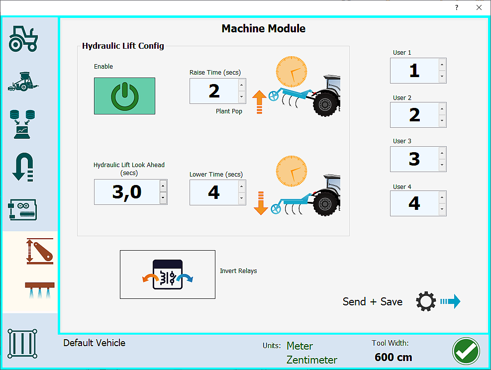
Enable hydraulic lift:
In the .ino the lines to be changed are:
/*
* Functions as below assigned to pins
0: -
1 thru 16: Section 1,Section 2,Section 3,Section 4,Section 5,Section 6,Section 7,Section 8,
Section 9, Section 10, Section 11, Section 12, Section 13, Section 14, Section 15, Section 16,
17,18 Hyd Up, Hyd Down,
19 Tramline,
20: Geo Stop
21,22,23 - unused so far*/
uint8_t pin = { 1,2,3,4,5,6,0,0,0, 0, 0, 0, 0, 0, 0, 0,17,18, 0, 0, 0, 0, 0, 0 };
The array pin has 24 entries out of which you may choose as many as relays are on your board. In fact the name “pin” is a bit unfortunate, this is more like an address or index scheme. Note: if you have a 16 relays board and an Arduino Nano then fill in 13 entries only.
Next step is configuring the output pins of the Arduino. As explained by @MylArti the Arduino Nano board supports only 13 output pins: D3 to D9 (see code below) and A0 to A5. Output pins D2, D10 to D13 may not be used since they are connected with the ENC28J60 Ethernet shield. If you have a USB setup without the ENC28J60, then this restriction does not apply.
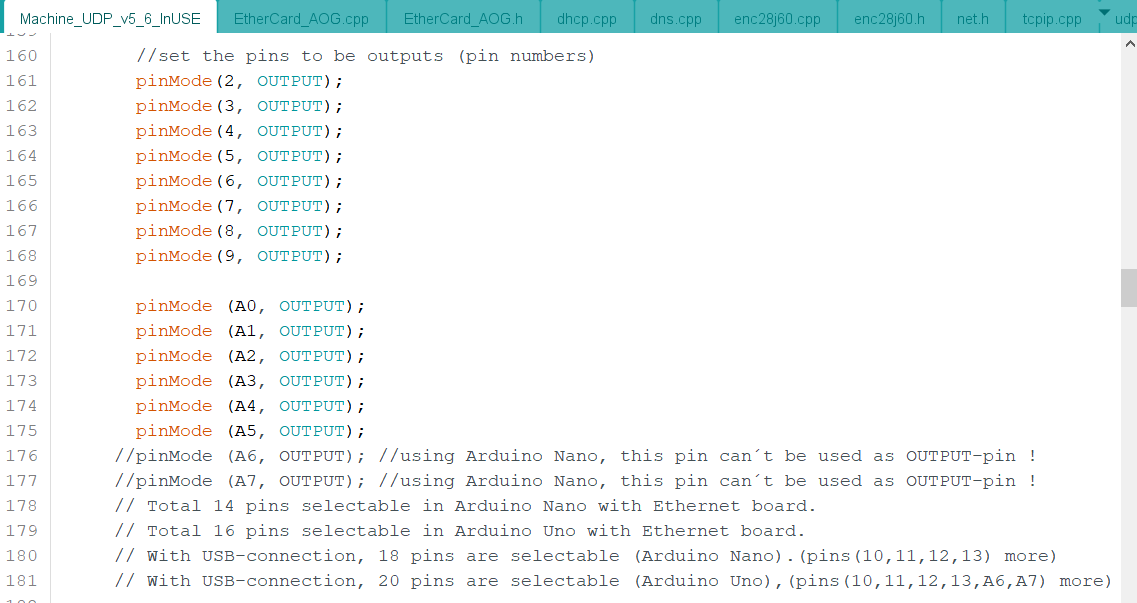
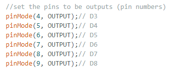
The number of pinMode() lines should correspond to the actual number of output pins used for triggering the relays:
//set the pins to be outputs (pin numbers)
pinMode(3, OUTPUT);// D3
pinMode(4, OUTPUT);// D4
pinMode(5, OUTPUT);// D5
pinMode(6, OUTPUT);// D6
pinMode(7, OUTPUT);// D7
pinMode(8, OUTPUT);// D8
pinMode(9, OUTPUT);// D9
pinMode(A0, OUTPUT);// A0
If you need more output pins then add additional lines pinMode(Ax, OUTPUT) with x ranging from 1 to 5.
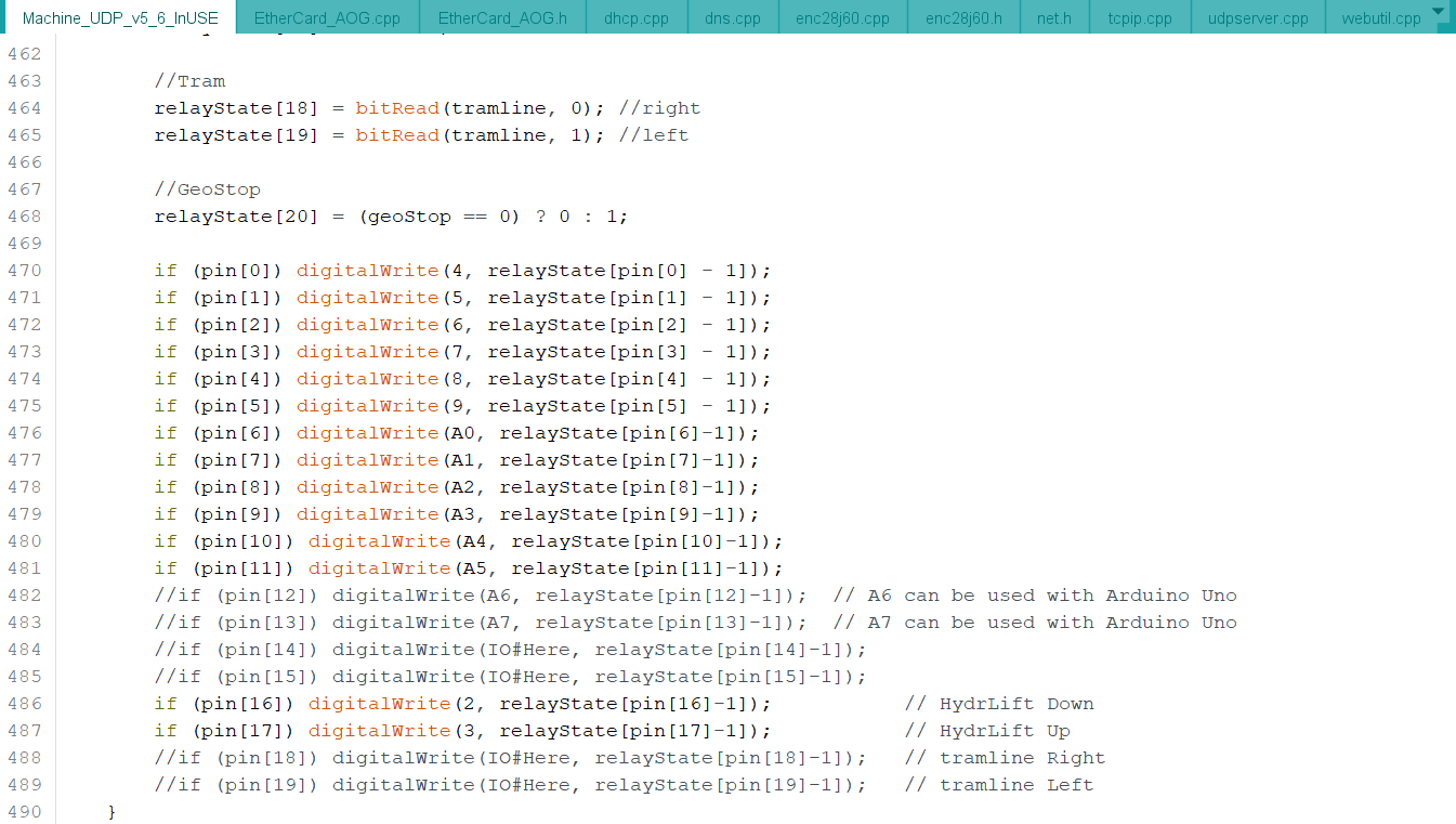
Furthermore, in the sketch you have to map the elements of the pin array to actual Arduino output pins (first argument of the digitalWrite() function). Again, there should be as many lines as configured output pins (see above).
Please note that counting in the pin array starts from 0.
if (pin[0]) digitalWrite(3, relayState[pin[0] - 1]);
if (pin[1]) digitalWrite(4, relayState[pin[1] - 1]);
if (pin[2]) digitalWrite(5, relayState[pin[2] - 1]);
if (pin[3]) digitalWrite(6, relayState[pin[3] - 1]);
if (pin[4]) digitalWrite(7, relayState[pin[4] - 1]);
if (pin[5]) digitalWrite(8, relayState[pin[5] - 1]);
//17,18 Hyd Up, Hyd Down
if (pin[16]) digitalWrite(9, relayState[pin[16]-1]);
if (pin[17]) digitalWrite(A0, relayState[pin[17]-1]);
Finally, in AgOpenGPS you have to map elements of the pin array from the .ino code to sections and other functions:
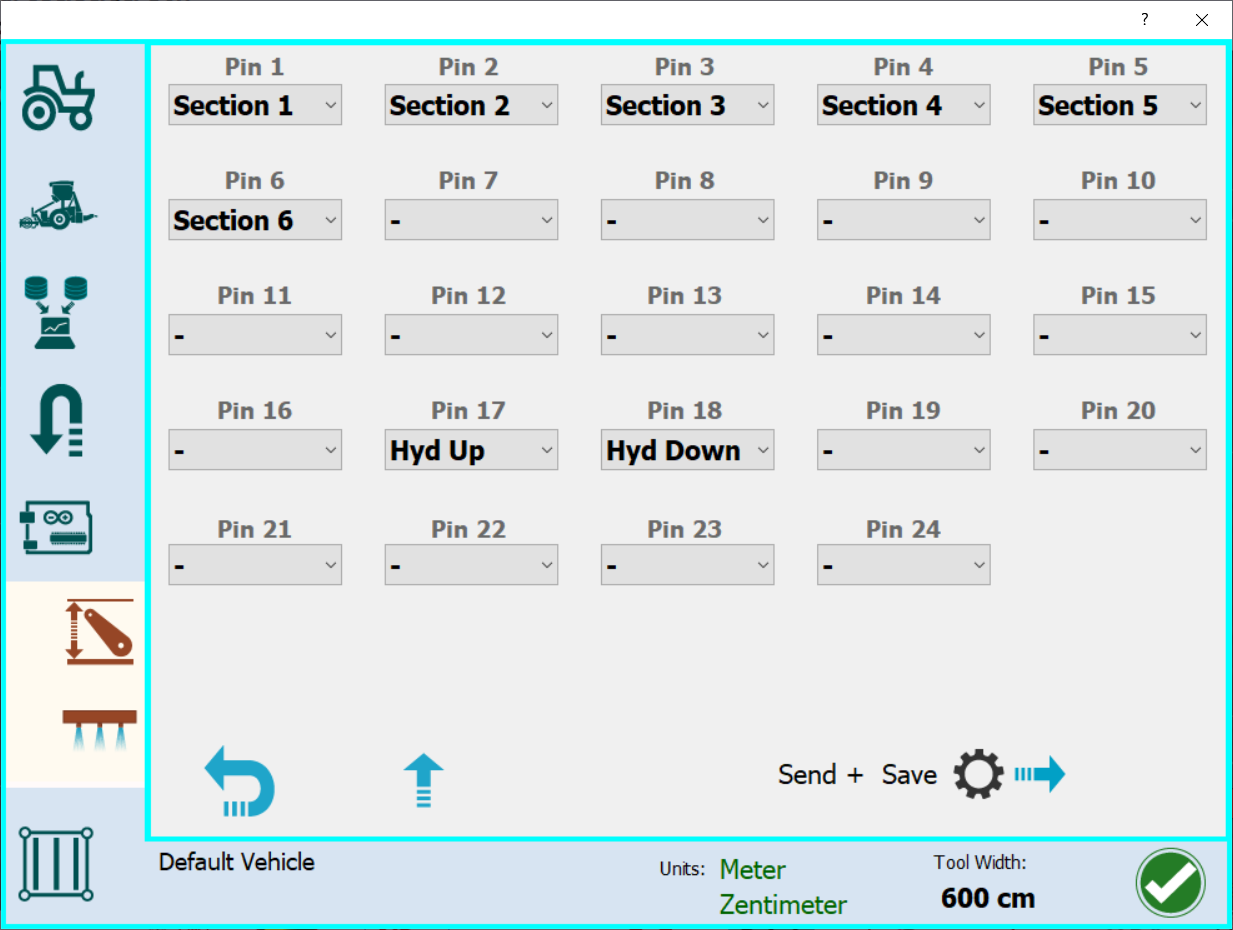
6 Likes
That is probably my problem. I didn’t see/ or forgot about last screen. I didn’t assign sections there. I will check that out.
Does INO need altered if you set sections and pins in AOG?
Is this in wiki? I haven’t found much info on machine setup. Thank you!
Well, it depends on your plans. If you only want to increase or decrease the number of sections within the configured limits then there is no need to touch the .ino.
If you want replace sections with hyd. up/dow (i.e. Pin 17 or above) and vice versa because e.g. you are running out of sections then you will have to edit the sketch.
1 Like
I tried and only can get 6 relays to work. I used newest INO and 5.7.2. not sure what I’m doing wrong. I assigned sections 1-12 on pins 1-12. Then 1-12 again on pins 13-24. Just to try to get all outputs working. Only have d4-d9 that turn on relays. Any ideas? I also changed version # for eeprom.
@D0824 where is the information, or wiki on machine udp besides this post?
Where is information on setting this up? Thanks
Edit: I see the information I was giving out had already been explained on here. Should’ve read the whole thread
2 Likes
-Deleted-
If I’m not wrong then a wiki is in preparation but not yet available.
Without further information it is nearly impossible to help you. Which Arduino? Which Ethernet shield? Which relay-board? How does your cabling look like? Which lines of the code have you adjusted? We need to see the lines which I explained above in detail.
Sorry, I thought info and pic was in this thread. It’s in another. Nano, enc28j60, 16 channel relay board.
I need to try again. I had everything working, but didn’t set pins in AOG. I’ll try it again with working sketch and setting pins.
I thought with standard sketch, could just set pins for 12 sections. Only 6 work.
Main problem I was having was working sketch was written over while changing coverage %, or timing. Thanks for help. I just need to spend more time with it. I will just unplug Ethernet adapter while making those changes if I can’t figure out.
Thanks
Here are the Arduino Nano pin names:
With the ENC28J60 Ethernet shield attached to the Arduino Nano only 13 section control relays can be triggered. Nano output pins D2 and D10 to D13 are used by this shield and may not be assigned.
Connect IN1 to IN7 of the relay-board with D3 to D9.
Connect IN8 to IN13 of the relay-board with A0 to A5 (equal to D14 to D19).
Then change the sketch as follows:
/*
Functions as below assigned to pins
0: -
1 thru 16: Section 1,Section 2,Section 3,Section 4,Section 5,Section 6,Section 7,Section 8,
Section 9, Section 10, Section 11, Section 12, Section 13, Section 14, Section 15, Section 16,
17,18 Hyd Up, Hyd Down,
19 Tramline,
20: Geo Stop
21,22,23 - unused so far*/
uint8_t pin = { 1,2,3,4,5,6,7,8,9,10,11,12,13, 0, 0, 0, 0, 0, 0, 0, 0, 0, 0, 0 };
//set the pins to be outputs (pin numbers)
pinMode(3, OUTPUT);// D3
pinMode(4, OUTPUT);// D4
pinMode(5, OUTPUT);// D5
pinMode(6, OUTPUT);// D6
pinMode(7, OUTPUT);// D7
pinMode(8, OUTPUT);// D8
pinMode(9, OUTPUT);// D9
pinMode(A0, OUTPUT);
pinMode(A1, OUTPUT);
pinMode(A2, OUTPUT);
pinMode(A3, OUTPUT);
pinMode(A4, OUTPUT);
pinMode(A5, OUTPUT);
if (pin[0]) digitalWrite(3, relayState[pin[0] - 1]);
if (pin[1]) digitalWrite(4, relayState[pin[1] - 1]);
if (pin[2]) digitalWrite(5, relayState[pin[2] - 1]);
if (pin[3]) digitalWrite(6, relayState[pin[3] - 1]);
if (pin[4]) digitalWrite(7, relayState[pin[4] - 1]);
if (pin[5]) digitalWrite(8, relayState[pin[5] - 1]);
if (pin[6]) digitalWrite(9, relayState[pin[6] - 1]);
if (pin[7]) digitalWrite(A0, relayState[pin[7] - 1]);
if (pin[8]) digitalWrite(A1, relayState[pin[8] - 1]);
if (pin[9]) digitalWrite(A2, relayState[pin[9] - 1]);
if (pin[10]) digitalWrite(A3, relayState[pin[10] - 1]);
if (pin[11]) digitalWrite(A4, relayState[pin[11] - 1]);
if (pin[12]) digitalWrite(A5, relayState[pin[12] - 1]);
Finally, in AOG map “Section 1” - “Section 13” to “Pin 1” - “Pin 13”. That’s it.
3 Likes
The short answer is, you can’t use the pins used for the enc28j60 for section control.
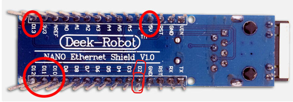
These pins cannot be used
Hello,
first of all, thank you for your information. This was very useful for me.
There is one more question.
Do you know what and where I need to add something in the sketch so that when the first section is turned on, the main valve (switch) is also turned on? Likewise, the main valve (switch) should turn off when the last section is turned off.
I have defined 5 sections on D3 to D7. I’m using Machine_UDP_v5 sketch dated March 2023.
D8 is defined as Section 6 (Main Valve/Switch).
Thank you for hints.
Without warranty, I couldn’t test this. The idea is to check if one of the 5 sections is active (logical or). In AOG only assign 5 sections, the main valve is not controlled by AOG.
// 6 sections
uint8_t pin = { 1,2,3,4,5,6,0,0,0, 0, 0, 0, 0, 0, 0, 0, 0, 0, 0, 0, 0, 0, 0, 0 };
[…]
pinMode(4, OUTPUT);
pinMode(5, OUTPUT);
pinMode(6, OUTPUT);
pinMode(7, OUTPUT);
pinMode(8, OUTPUT);
pinMode(9, OUTPUT);
[…]
// 5 sections
if (pin[0]) digitalWrite(4, relayState[pin[0] - 1]);
if (pin[1]) digitalWrite(5, relayState[pin[1] - 1]);
if (pin[2]) digitalWrite(6, relayState[pin[2] - 1]);
if (pin[3]) digitalWrite(7, relayState[pin[3] - 1]);
if (pin[4]) digitalWrite(8, relayState[pin[4] - 1]);// main valve
// the addressing scheme is a bit weird, but should be understandable
relayState[pin[5] - 1] = relayState[pin[0] - 1] || relayState[pin[1] - 1] || relayState[pin[2] - 1] || relayState[pin[3] - 1] || relayState[pin[4] - 1];
if (pin[5]) digitalWrite(9, relayState[pin[5] - 1]);
Thank you very much.
I tried to make a or-function but I didn’t know what to include. Your suggestion makes sense to me.
I will test it in the next few weeks and give feedback here.