In the end I could solve my problems, so maybe others find the explanations below useful. Screenshots/code are from AgOpenGPS 5.7.2 and Machine_UDP_v5_6.ino (in release 5.6.34). Example is for an 8-relays-board for 6 sections and hydraulic up/down.
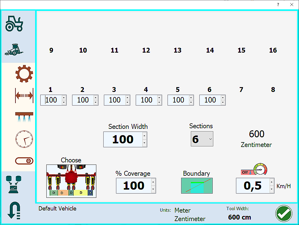
Set sections and section widths:
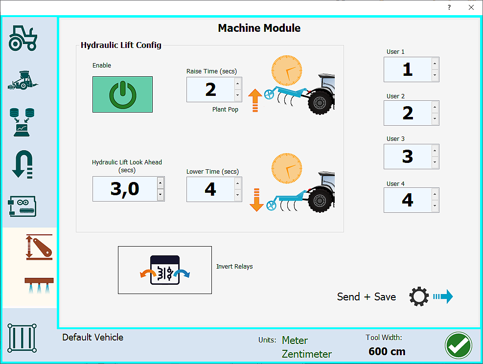
Enable hydraulic lift:
In the .ino the lines to be changed are:
/*
* Functions as below assigned to pins
0: -
1 thru 16: Section 1,Section 2,Section 3,Section 4,Section 5,Section 6,Section 7,Section 8,
Section 9, Section 10, Section 11, Section 12, Section 13, Section 14, Section 15, Section 16,
17,18 Hyd Up, Hyd Down,
19 Tramline,
20: Geo Stop
21,22,23 - unused so far*/
uint8_t pin = { 1,2,3,4,5,6,0,0,0, 0, 0, 0, 0, 0, 0, 0,17,18, 0, 0, 0, 0, 0, 0 };
The array pin has 24 entries out of which you may choose as many as relays are on your board. In fact the name “pin” is a bit unfortunate, this is more like an address or index scheme. Note: if you have a 16 relays board and an Arduino Nano then fill in 13 entries only.
Next step is configuring the output pins of the Arduino. As explained by @MylArti the Arduino Nano board supports only 13 output pins: D3 to D9 (see code below) and A0 to A5. Output pins D2, D10 to D13 may not be used since they are connected with the ENC28J60 Ethernet shield. If you have a USB setup without the ENC28J60, then this restriction does not apply.
The number of pinMode() lines should correspond to the actual number of output pins used for triggering the relays:
//set the pins to be outputs (pin numbers)
pinMode(3, OUTPUT);// D3
pinMode(4, OUTPUT);// D4
pinMode(5, OUTPUT);// D5
pinMode(6, OUTPUT);// D6
pinMode(7, OUTPUT);// D7
pinMode(8, OUTPUT);// D8
pinMode(9, OUTPUT);// D9
pinMode(A0, OUTPUT);// A0
If you need more output pins then add additional lines pinMode(Ax, OUTPUT) with x ranging from 1 to 5.
Furthermore, in the sketch you have to map the elements of the pin array to actual Arduino output pins (first argument of the digitalWrite() function). Again, there should be as many lines as configured output pins (see above).
Please note that counting in the pin array starts from 0.
if (pin[0]) digitalWrite(3, relayState[pin[0] - 1]);
if (pin[1]) digitalWrite(4, relayState[pin[1] - 1]);
if (pin[2]) digitalWrite(5, relayState[pin[2] - 1]);
if (pin[3]) digitalWrite(6, relayState[pin[3] - 1]);
if (pin[4]) digitalWrite(7, relayState[pin[4] - 1]);
if (pin[5]) digitalWrite(8, relayState[pin[5] - 1]);
//17,18 Hyd Up, Hyd Down
if (pin[16]) digitalWrite(9, relayState[pin[16]-1]);
if (pin[17]) digitalWrite(A0, relayState[pin[17]-1]);
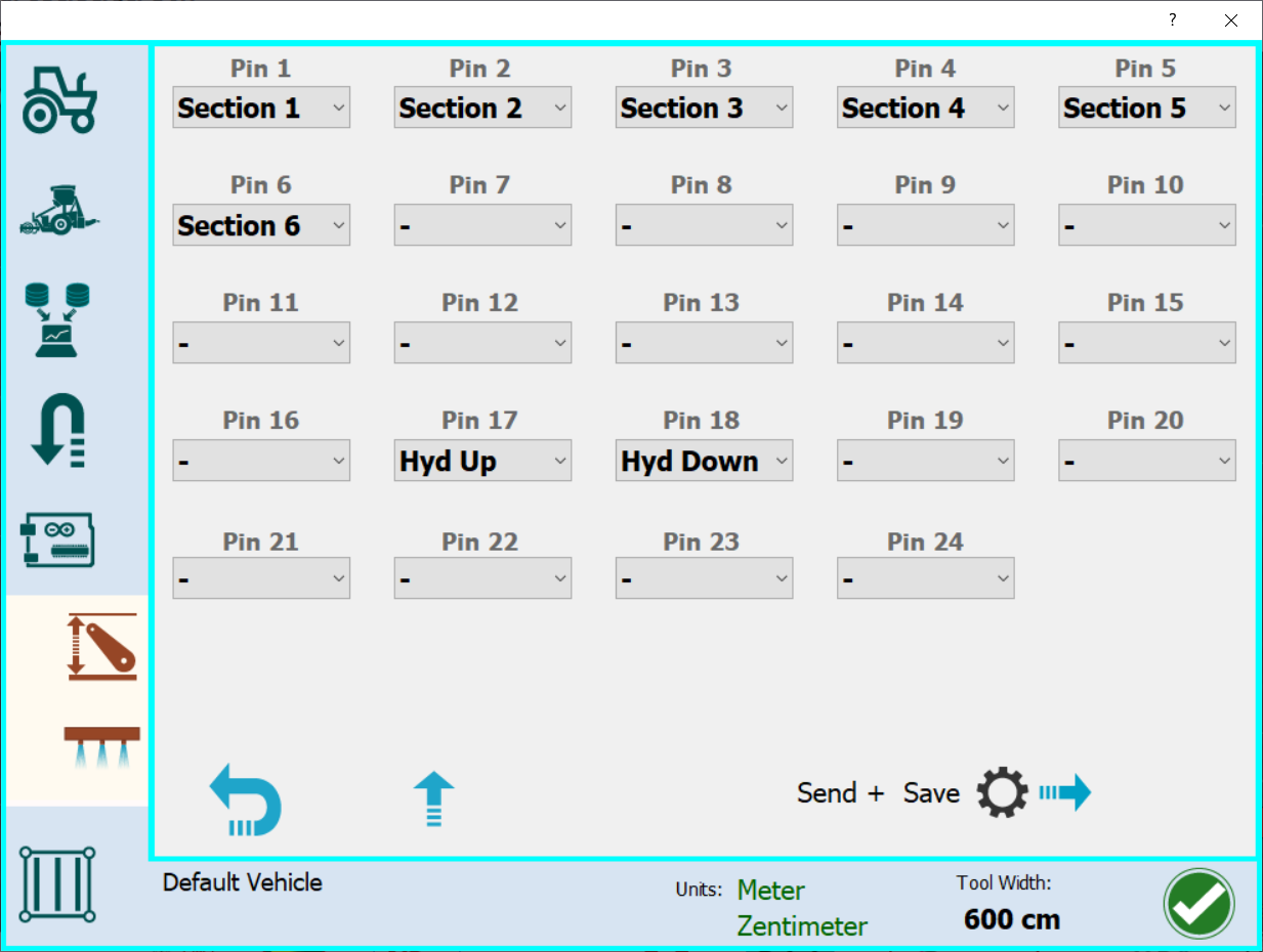
Finally, in AgOpenGPS you have to map elements of the pin array from the .ino code to sections and other functions: