about the IBT2: Yes, you can mount several drivers in parallel. You can also use the two channels of one board as one. But anyway you’ll have to modify the China boards by adding thermally conductive pads between heatsink and board.
what do you mean ? you have to isolate the heatsink when you use more than one ? i see the ibt2 hat a price of 3 to 4 € at aliexpresss thats cheap
I took off the heatsink and added computer heat paste between heatsink and ibt_2.
THERE were nothing there on mine, and heatzink didn’t even fit well.
That is why ![]()
1 Like
heb jij een werkende aog op je traktor staan ?
ik wil werken met een olie pomp parrallel op de stuurcylinder enig idee of het kan werken ?
1 Like
needed Google for the translation of the 2nd sentence… ![]()
I personally have no experience with hydraulic control, so I’ll have to let the others answer.
Just from the electrical point of view, a hydraulic pump will need very high currents, so that an external motor driver next to motor and battery and suitable wiring is absolutly necessary.
And please mind safety issues if you modify the hydraulic steering.
Nl:
Als je niet teveel in je cabine wil prutsen met een stuurmotor zou ik toch voor een ventielblok gaan, zoals hierboven ook gezegd heb je dan wel een hele zware elektromotor nodig om die pomp aan te drijven.
En:
If you dont want to mess around in the cab i would go for proportional valves like said above the pump would need quite a lot of power.
die hydrolische klep heb ik niet op voorraad en ik denk dat een propertionaal ventiel niet van de goedkopste is en dan heb ik nog van ergens de oliedruk nodig waardoor ik een kring kwijt ben
die motor met pomp ligt op het schap 24v 2500w (orgineel van een servstuur van een vorklift)
ik ga is proberen wat die op 12 volt doet heeft die nog steeds 600w
I do not have that hydrolic valve in stock and I think that a cleanional valve is not of the most cheap and then I still need the oil pressure from somewhere so that I have lost a circuit
that motor with pump is on the shelf 24v 2500w (original of a servo steer of a fork lift)
i’m going to try what that does at 12 volts which still has 600w
Hi, I’ve been testing tiles for 2 months. Everything works, however there is a problem with the usb hub. After connecting 2x ardusimple + esp 32 there is a voltage drop, m12 gnss connector. “u19” removed. An additional power supply is needed. Can this be improved in some way?
I have not heard from @GoRoNb
in awhile. I’ve been trying to get ahold of him myself. I hope all is well.
This site is pretty seasonal, he might be on the tail end of helping his friend with seeding. Also I think read somewhere he is a hardware engineer for a big company, so he may be on project too.
Hello,
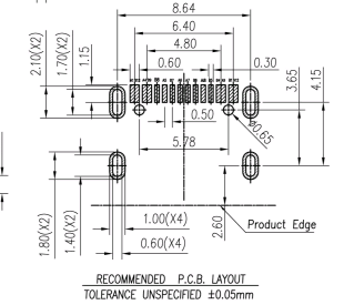
Could you share the p/n for USB-C? After ordering PCB, JLC made me aware that PCB layout is made for THT type element, whereas BoM refers to an old part ( C709357)
PCB layout for THT
PCB layout needed for C709357
Thanks!
Hello Matias,
I’ve faced the same problem/issue. In my case though JLC said that “Q8 is not open for soldering”, I’m not an expert but I guess soldermask is not removed in this area and that doesn’t allow adding solder paste and soldering.
@GoRoNb maybe worth including this small correction in a new release?
Best regards
Maybe I’m wrong but I think this part should be wthat you are searching for: KH-TYPE-C-16P
That’s the part currently referenced in BoM. To me it looks like the THT element should have pins perpendicular to the board, sth. like this one (just not sure about pins):
Follow the directions from jlcpcb. Add the solder mask and solder paste. The usb-c socket from the link is incorrect. During the update, the project was changed from smd to tht. I need to find a symbol. I’ll let you know
gniazdo USB typ C 3.1 16pin PCB sklep.naprawalaptopa.pl this socket will fit. regards. In case of problems, write. There is still a long way to go to launch this tile.
1 Like
Many thanks Matias for the link and the hint on the pcb.
PCB is ordered now, however strangely enough in my case jlcpcb was not willing to add solder mask + paste to Q8 (though it shouldn’t be a problem to manually correct it).
I’m at the very beginning of the assembly process so surely will come back for some advice ![]()
Using GoRoNb’s idea, here is some test code that works with a Teensy 4.1, a MAX3485CPA+ and a RS485 8 relay module. Only one relay can be set within 25ms, but it is non-blocking by doing one at a time.
#define SendEnablePin 6
#define Interval 1000
unsigned long ChangeTime;
byte LoRelays = 0;

byte CRC[] = { 0xD9, 0x6A, 0x29, 0x6A, 0x78, 0xAA, 0xC9, 0x6B, 0x98, 0xAB, 0x68, 0xAB, 0x39, 0x6B, 0x09, 0x68,
0xD9, 0x9A, 0x29, 0x9A, 0x78, 0x5A, 0xC9, 0x9B, 0x98, 0x5B, 0x68, 0x5B, 0x39, 0x9B, 0x09, 0x98 };

void setup()
{
    Serial1.begin(9600);
    pinMode(SendEnablePin, OUTPUT);
    digitalWrite(SendEnablePin, HIGH);
}

void loop()
{
    SetRelays(0,LoRelays);
    if (millis() - ChangeTime > Interval)
    {
        ChangeTime = millis();
        if (LoRelays)
        {
            //LoRelays = LoRelays/2;
            LoRelays = 0;
        }
        else
        {
            LoRelays = 255;
        }
    }
}

bool RelayStatus[16];
bool BitState;
byte SwitchedPowerRelay = 5;
unsigned long LastRelaySend;

void SetRelays(byte HiByte, byte LoByte)
{
    if (millis() - LastRelaySend > 30)
    {
        LastRelaySend = millis();
        for (int i = 0; i < 16; i++)
        {
            if (i == SwitchedPowerRelay)
            {
                BitState = HIGH;
            }
            else if (i < 8)
            {
                BitState = bitRead(LoByte, i);
            }
            else
            {
                BitState = bitRead(HiByte, i - 8);
            }

            if (RelayStatus[i] != BitState)
            {
                WriteRelay(i + 1, BitState);
                RelayStatus[i] = BitState;
                break;
            }
        }
    }
}

void WriteRelay(byte ID, byte State)
{
    byte SendArray[] = { 1,6,0,ID,2 - State,0,CRC[2 * ID + 16 * State - 2],CRC[2 * ID + 16 * State - 1] };
    Serial1.write(SendArray, sizeof(SendArray));
}
Here is a photo of my test with the rooftop module with dual F9P. It works, just had to switch the F9P’s in place from my first interpretation. So contrary to the photo, ‘ARDU1’ on the PCB is for the right F9P! Pixhawk cables I found were mirrored so I had to rewire them.
The LEDs and buttons on the PCB appear to do nothing.
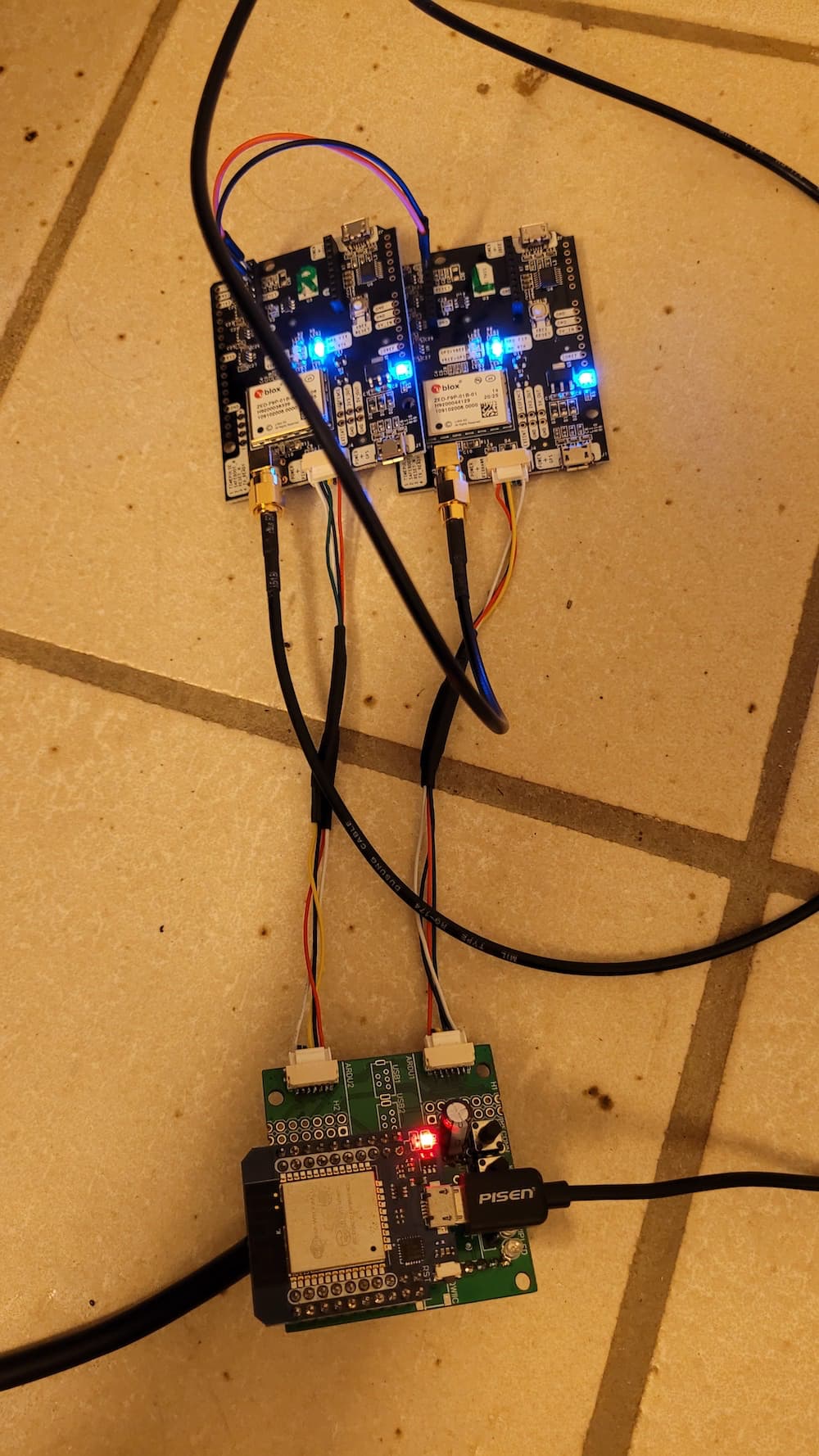
As I will communicate with USB, should I worry about feeding the module with 12V? In the schematic it says ‘optional’…
Does someone know if the WEMOS D1 mini ESP32 can handle the two simpleRTK2B (each 600 mW according to ardusimple)? In a short test it worked fine for an hour.
@GoRoNb
EDIT: specs say * Voltage Reg. : RT9013 500mA LDO
module itself uses 80 mA + 2* 120 mA of simpleRTK2B = ± 320 mA so within specs?
1 Like
Hi Karel,
happy to hear it is working!
The board is not V1.3, is it?
Yes, you may supply with 12V when you put one the those China boards with a MP1584EN in. There’s a place for it.
The ASs get 5V, don’t they? So the Wemos only does 3.3V for itself. Each AS has a 3.3V regulator for its own - should be fine even for summertime.
Seems Matthias removed the support for pushbuttons in his firmware, so yes, doesn’t work so far. But you should be able to configure one LED for WiFi in the web interface.
BR
Gorm