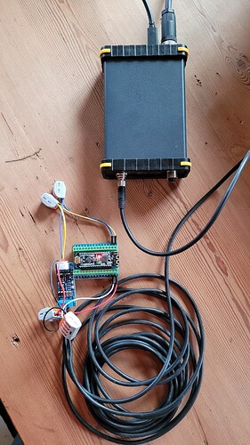
AFAIR I realized the swap and changed it already, so sorry for the inconvinience…
all stuff is installed and working
where can i find a good guide for making the first field activity
create a field make the first around for the exact borders ect how do i use agopengps v5
do you work with v5 moonshine ? dutch is so much eazyer to talk
no in this thread here - it’s about the Central Unit V1.x and supporting PCBs only… ![]()
Enter this page and watch the videos, they will help you a lot.
https://www.youtube.com/channel/UC62XU8ZdXX_ALNYKRAWkFeg
Hello @GoRoNb , could you tell us what would be needed to make the RS485 port come alive? I am complete novice on this.
I was thinking about using it for simply connecting an arduino nano over a distance of 5m as machine control. I have a XY-K485 module like this one hooked up with the A and B wire on one side going towards the autosteer PCB and TX,RX going to the arduino. The GND and 5V coming from the autosteer box serve as power for both the module and the arduino. The arduino is powered and on the converter module the TX led flashes, but nothing happens in Windows. I guess a new USB-device should pop up and normal communication should be possible just like any other USB device?
BTW I have version 1.4 of the autosteer PCB working.
so, first of all, I’m quite a fan of RS485 due to its robustness and simplicity. The difference to “normal” Rx/Tx is, that the sender needs to tell the RS485 driver, when is has to send. It’s half-duplex, so one one unit may send at one time. On the other hand, you can talk to 32 units at the same time.
So, in short, you have to set the signal DIR485 (pin 2+3 of RS485 driver) to 1 before starting sending and set it back to 0 after the last byte has been sent. Mind, that sending takes some time, so wait a small time after putting the last byte to the output register.
Modern µC have a dedicated pin for that, but the Atmel does not have that and the ESP only has it for the port, that is usually blocked for USB.
On the central unit 1.x, RS485 is connected to a USB serial device. That guy handels all for itself, so you don’t need to care for anything. So, when opening HTerm or whatever and sending something to that COM port, you should see led “TX485” blinking.
You are right. The COM port was there all along in Device manager next to the built-in arduino one! I somehow thought all of them come in pairs (bluetooth ones do).
So in fact the traffic is one-way, modules on the far end are for ‘listening’ only? Or is two-way possible when only 1 device is attached?
We could wire several of these RS485-TTL adapters on the far end with devices all listening to what the COM port is attached to? e.g. machine-USB in AgIO, or other, but one source only.
RS485 is half-duplex, so two-way-communication is possible of cause, also to up to 32 units. But it’s like 32 people in a room - doesn’t work, when more than one is speaking at the same time…
Yes, works out of the box for Central Unit 1.x and 2.x. On the client side, you need an addional wire between the driver and the µC for telling the driver, when is shall switch for sending. Sending is like that:
digitalWrite(Dir485, 1);
Serial.print(“Hello AgOpenGPS”);
delay(1);
digitalWrite(Dir485, 0);
This shield looks interesting, though it is made for ‘Arduino MKR’ boards:
In combination with this library it seems that it could take care of two-way communication. Though unclear to me yet if it automatically works with multiple active devices too.
there’s no technical difference, if you talk to one or to 31. For example, you can put 4 Modbus relay modules on that lines as well.
It must “just” be ensured, that only one is sending at a time, so unlike CAN (= multi-master), RS485 is normally a master-slaves-system.
Hi @kareldew, I didn’t answer, why the suggest module XY-K485 works w/o DIR485: The principle here is a litte bit like CAN: when you apply the “active” level on TxD, which is low, then the driver is active. When TxD returns to high again - no matter, if the byte is over or just a high bit should be send - , the driver remains active for a very short moment and then enters tristate mode, hoping that the bus termination resistors will hold the bus to idle level.
This is non-standard, but works not too bad for short wires. So worth a try, but the shield is definitely the better choice - also offering an power supply input up to 24V.
With 2 way communication is there a blocking delay waiting for a reply? How long is the delay?
This picture shows the relation of Tx and DIR485 (here shown as “RTS”, which is mostly used for that in modern µCs):

So, DIR485 should return low after the stop bit has been sent. The time doesn’t matter so much, as long as the next participant on the bus doesn’t start. So, there must be a planning of the timing. It can be simply master-slave, so that the slave is only allowed to send when asked, or like this proposal for AOG here:
(GNSS packet-to-GNSS packet is exactly 100msec for Ardusimple)
For more general information, there’s a nice application note from ADI.
The delay matters to the rest of the autosteer code.
Yes, it can improve the steering! In fact, there’s no difference from standard UART Rx/Tx, because sending and receiving is daisy-chained anyway @ AOG. The GNSS information is what AOG locks to. Then AOG calculates data for steering, sends it out and receives an answer from the steer unit immediately. This is a disadvantage, because the WAS and IMU information is quite old when the next GNSS information arrives. With the steering unit listening to the same bus, it can do the timing in a way, that this information comes quite close before the GNSS packet.
I can confirm it works two-way in a 10 minute test with this xy-k485 adapter attached to RX0-TX0 of an ESP32 with MTZ section control code in USB-mode (5 meter 4 wire cable, not twisted nor shielded). I couldn’t find common RS485-shields for ESP32 so far.
What power usage is the ‘battery 5V+ fused’ supply on the board of the RS485 port built for? Looking in the schematic it is a ‘TPS54302’ buck converter, in datasheet it says capable of 3A. So I guess I can reliably attach an ESP32 with some peripherals?
the wires should be close to each other - you won’t like having a loop antenna. But that’s really all for so small distances. Perfectly fine, if you’re using a single cable.
Yes, says 3A. I’m always scared, so I say 1.5A, but you’ll need less than 400mA for ESP32 + dual-Ardusimple - so no prob at all. Should mention that the fuse is accidentially a 6V type, so if you’re scared, too, replace it by e. g. BSMD0805-050-24V (slightly bigger package) or avoid shorts… ![]() The fuse will work anyway, but as a single-trip-fuse…
The fuse will work anyway, but as a single-trip-fuse… ![]()
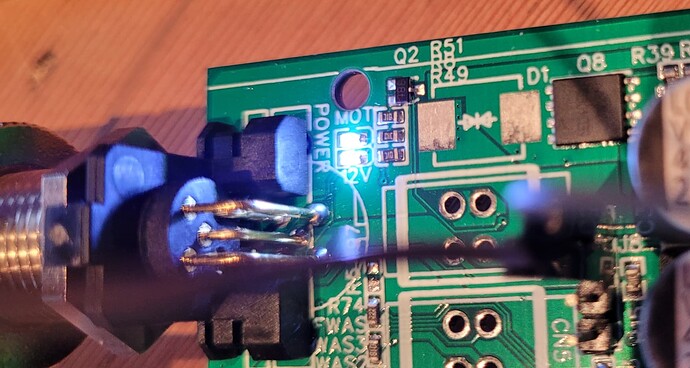
I was trying a suggestion from your functional description to include a on/off switch in the housing. If I fit it to pin 3-4 of J8 it only switches a LED on/off just below the 12V-led in left upper corner.
Is it maybe because the D1 or D2 part is missing on my board?
From github readme v1.x:
The fifth pin of the power plug may either be used for a protected digital output (jumper on 1-2 of J8) or as on-switching signal (jumper on 2-3 of J8). No high currents have to be switched – a small SPST switch is ok. A switch inside the housing would be connected to 3-4 of J8. If an external switch is used to cut of the supply directly, apply a jumper to 2-3 of J8.
@GoRoNb should we preferably mount D1, D2, D5, D6, D7 if not done by the board manufacturer? I see they are all for electric discharge protection. Before in this topic you said they are not mandatory. But best to mount them anyway for a robust system?
D1 and D2 are high-power trasient clamping diodes. Mandatory for all kind of industrial stuff, but likely not necessary here. It helps against peaks from lightnings e. g.
When the 12V LED is on and off, everything is fine. The reason, why the board does not power down is, that you supply by USB, I think. When doing that, you don’t need the 12V power supply block at all, so just place no switch. When you power down the tablet, the central unit is off, too (if USB is configured that way).
D5…7 are for ESD protection on CAN. You usually don’t need them as long as you don’t have open wire ends to touch.


