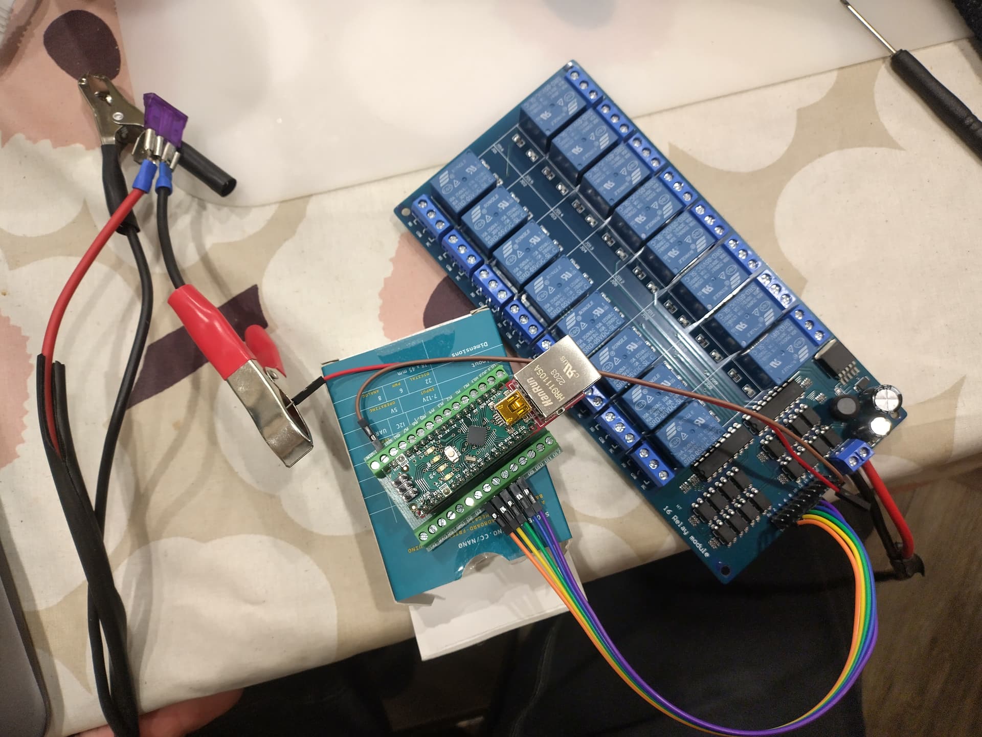
I was thinking of making section control for spayer. Now I have 16 relay module and nano with ethernet and terminal block shields.
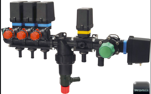
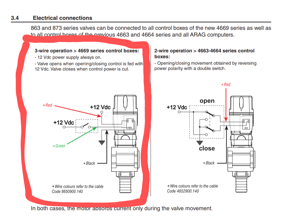
I was thinking of doing module between spayer control box and spayer. Section control module would have male and female sockets so nothing would need to be done outside of this and I could plug it between spayer and spayer controller. When all section are ON from spayer coltroller AOG would control sections by cutting each +12v that opens and closes valve. Maybe there could be one swich on top of this module what could power all relays(with diods) or set relays NC and cut 5v from nano and relay board, so I would be able to use spayer manually without AOG. Spayer has Arag valves and controller which has switches for 5 valves, pressure adjustment and all valves ON/OFF swich. I think each valve are controlled with one of the three wires what does into it, I will check this.
Is there easier and smarter way to do this? What is good for 12v → 5v? I don’t think that nano and few relays takes that much current.
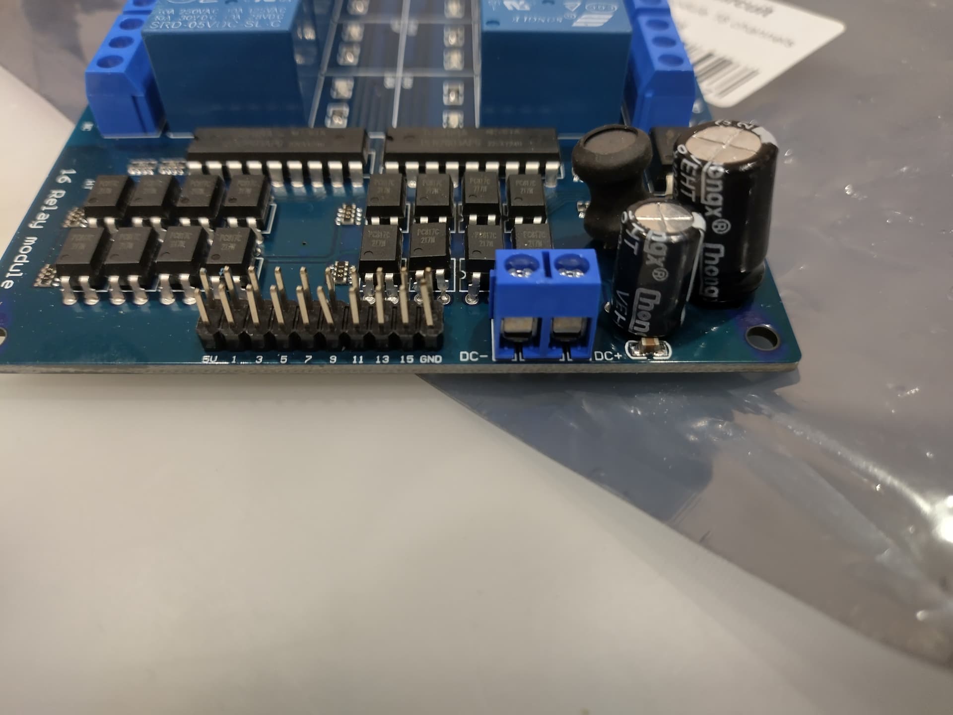
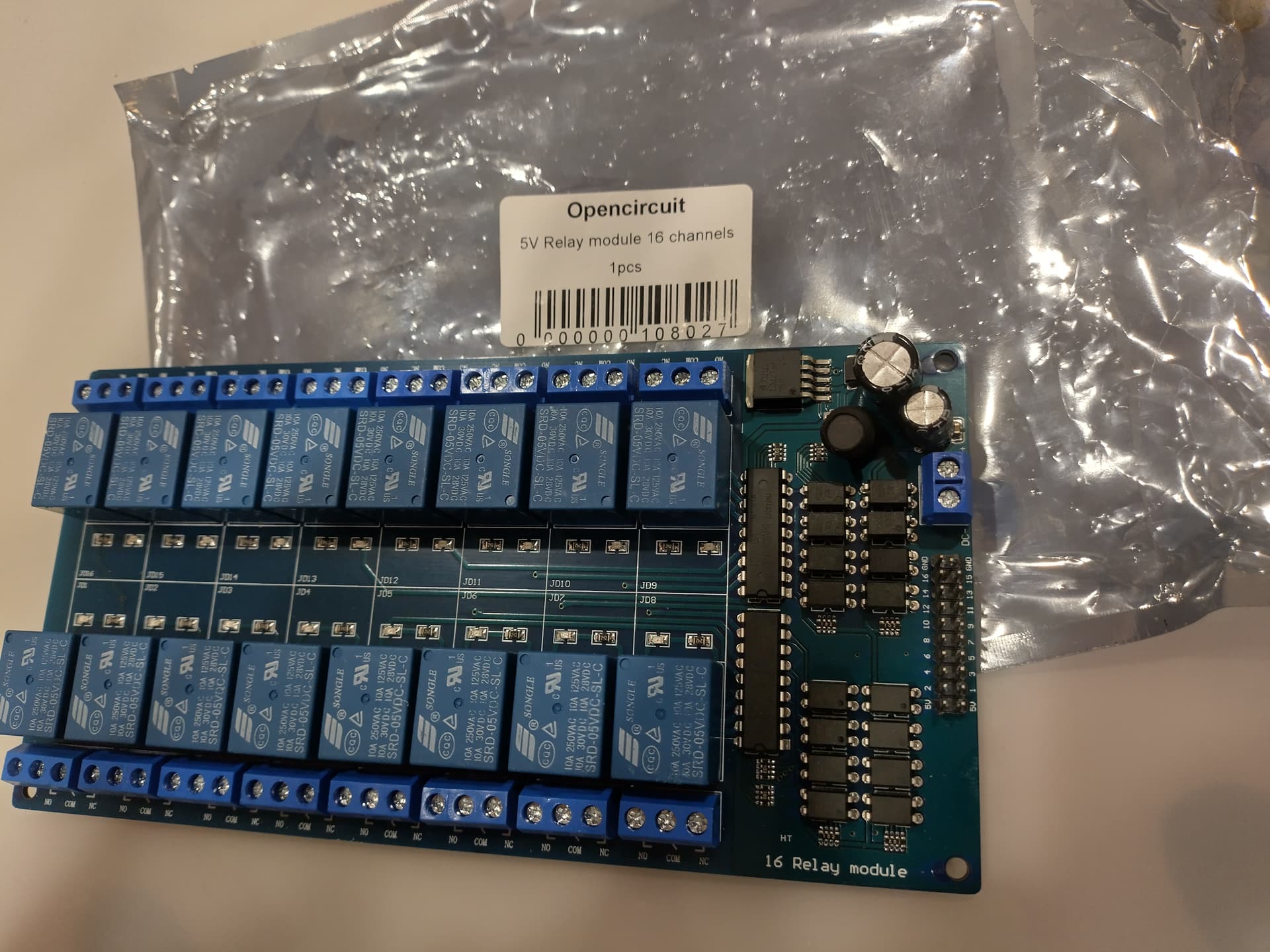
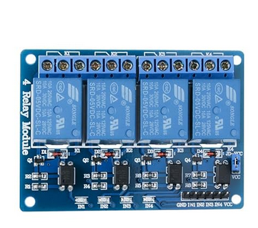
I ordered this a year ago. I can not find specs from this relay module enywhere but maybe some of you know If I can connect 12v from tractor to DC+ and DC- and power up nano from 5v PIN?
Edit: It has LM2596S -5.0 so I am more convinced that I could go It!
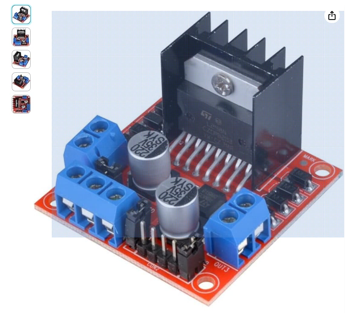
I have used similar relay cards (4 relays each) for my sprayer. After some time I replaced the proportional valve (pressure control) with PWM – H-Bridge amplifier ( L298N ). And it is working perfect. Selecting different PWM rates → result in an adjustable voltage to the motorized valve → results in adjustable moving speed for fine tuning the valve position (yellow one)!
One of H Bridge can handle 2 valves in both direction (equal to 4 relays), but much more sensitive if needed.
In the last 5 years, about 2 relays broke, and I had to replace each time the whole module. You can use smaller modules.
Now I am replacing all relays with H Bridges to avoid further problems.
Be aware to select at least a minimum PWM for a minimum Voltage to stable turn the Motorized valve. Too less voltage just produce heat in the motor without movement and can harm the devices.
Yes it has motorized valves. We don’t spray that much a year so section control with relays is a good start for us. Tractor we usually use for spaying is valtra direct. Although it is not “real CVT” I set engine rpm to match 540 in pto, set pressure from spayers controller and use cruise for speed. Often we use 100 litres per hectare so this accuracy is well enough for us.
This board has 16 relays and only be using 5 of those . If one relay breaks couldn´t I just change the cabling for an other relay
Of corse, that why its always better to take more relay boards price difference is negligible to 8 relays. You have space to upgrade or have contingency if one of relays fail. For motorized valve you use 2 relays per valve. One open other reverse to close. So you should have 6 left.
You can use USB because it feed nano with 5 v directly (does not have to go trough the voltage regulator)
There’s a 5V pin (no more no less) 3 pins beside the Vin
Yes I ment that 5V pin. This relay module has LM2596S 5.0 so would be okay for powerin 5V PIN in nano?
I have some problems with my usb to lan convert so I did not manage to make it work in laptop. But it works nicely with FZ-G1(it has lan) when I power nano from usb!!! Feels like victory already!!!
upload RC_ESP32 firmware with a usb cable. Subsequent updates can be uploaded over wifi. In a browser enter “192.168.100.1/update” to get to the update page.
What is the firmare? the file from first repositry?
Are there any recommnede values for Arag devices (valve, flowmeter, pressure sensor)?
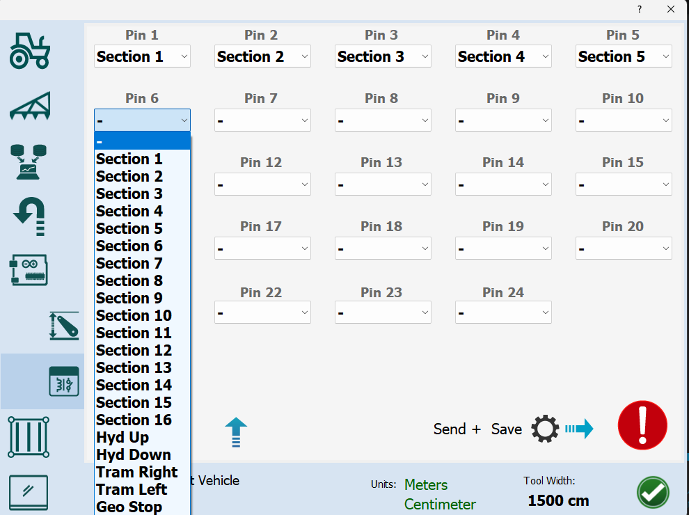
What should I set up in the system? against this section
The first repo is the software. The second is the hardware. The first has the hex files to upload. There is no connection to the machine page, setup is done on the rate app. I don’t know of any recommended values for Arag devices. Maybe there is someone that is using it that would know.
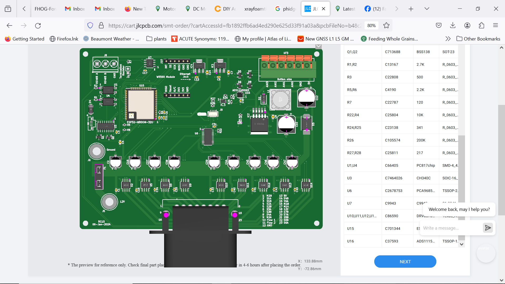
The first step is to upload the hex file using a usb cable. PCBsetup GitHub - SK21/PCBsetup: Setup software for AgOpengGPs rate control and steering modules. can upload the file. Next run the rate app and go to module config. From here you can set the subnet and upload it to the module. Next in module config select the RC15 pcb and upload the default settings. The next steps are the product settings, section width and number, and relay settings.