what am I doing wrong?
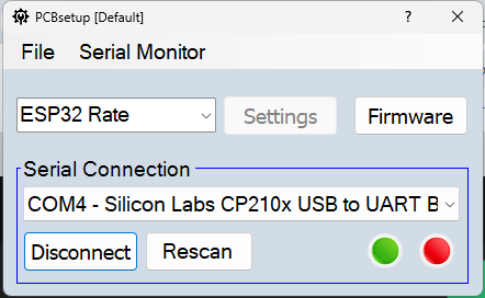
esp32 is detected as com4
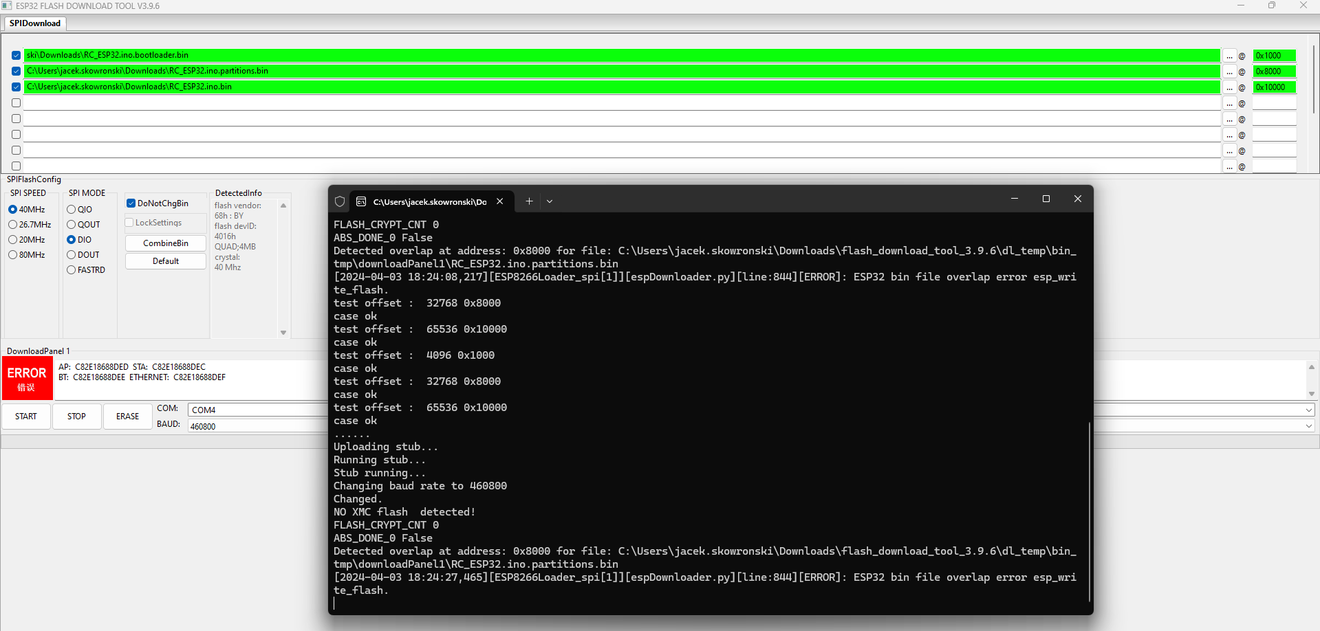
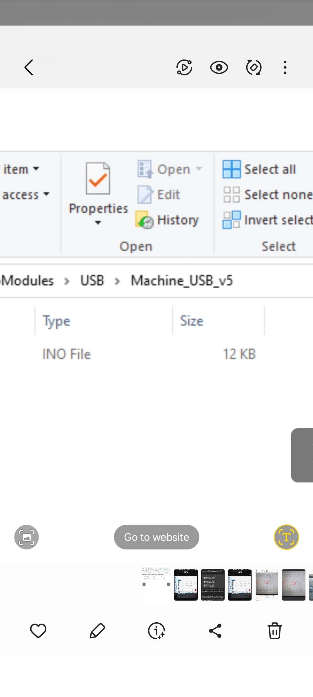
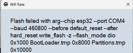
Than I choose firmware file - whatever I choose from those 3 files I get such an error
what am I doing wrong?
esp32 is detected as com4
Than I choose firmware file - whatever I choose from those 3 files I get such an error
when I try this tool
I get
the problem was with corrupted files
when I downloaded whole repository, than I can program esp32
@SK21
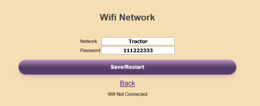
How can I connect esp32 to my wifi network?
Now I can provide network name and pass, than save, then arrow up and nothing change, the esp32 network still is 192.168.200, when my local wifi network is 192.168.0
What is the procedure?
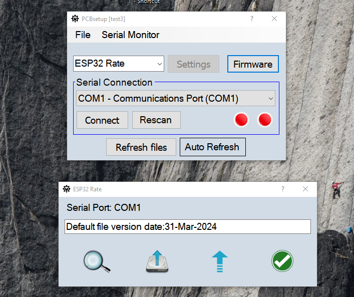
When you click the Firmware button the default file is already selected and ready to upload. It is included in the app. You can select different files if needed.
Here are some revised instructions. Let me know if this helps.
RC15 Installation.pdf (109.4 KB)
Thanks for instruction.
Step 2:
2. To connect to a wifi network go to the web interface/Network. Enter the network
configuration. The ESP32 will restart and attempt to connect. After 10 unsuccessful
attempts it will switch to AP mode
If the esp32 starts with 192.168.200.1 - then the address should be: 192.168.200.1/Network ???
There was some tab on the 192.168.200.1 called network - but when I change anything it does not restart or even try to connect to my wifi router.
Is that possible that my wifi is to secure for esp32? I use WPA2-personal and password of 8 characters.
On my network I have other ESP32 for intelligent heating system called HomeAssistant. And this ESP32 works fine in my network.
Just go to 192.168.200.1. Press the Network button.On the network page enter the network name and password. Press Save and the ESP32 should restart and attempt to connect to the network.
Now seems to be working.
This is a clean test on the esp32, now I’m waiting for my pcb
Thanks and regards
yacenty
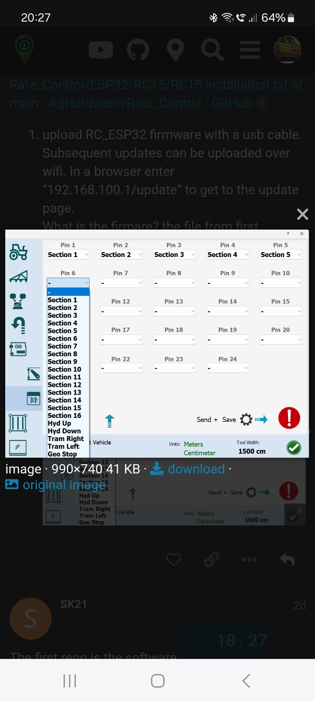
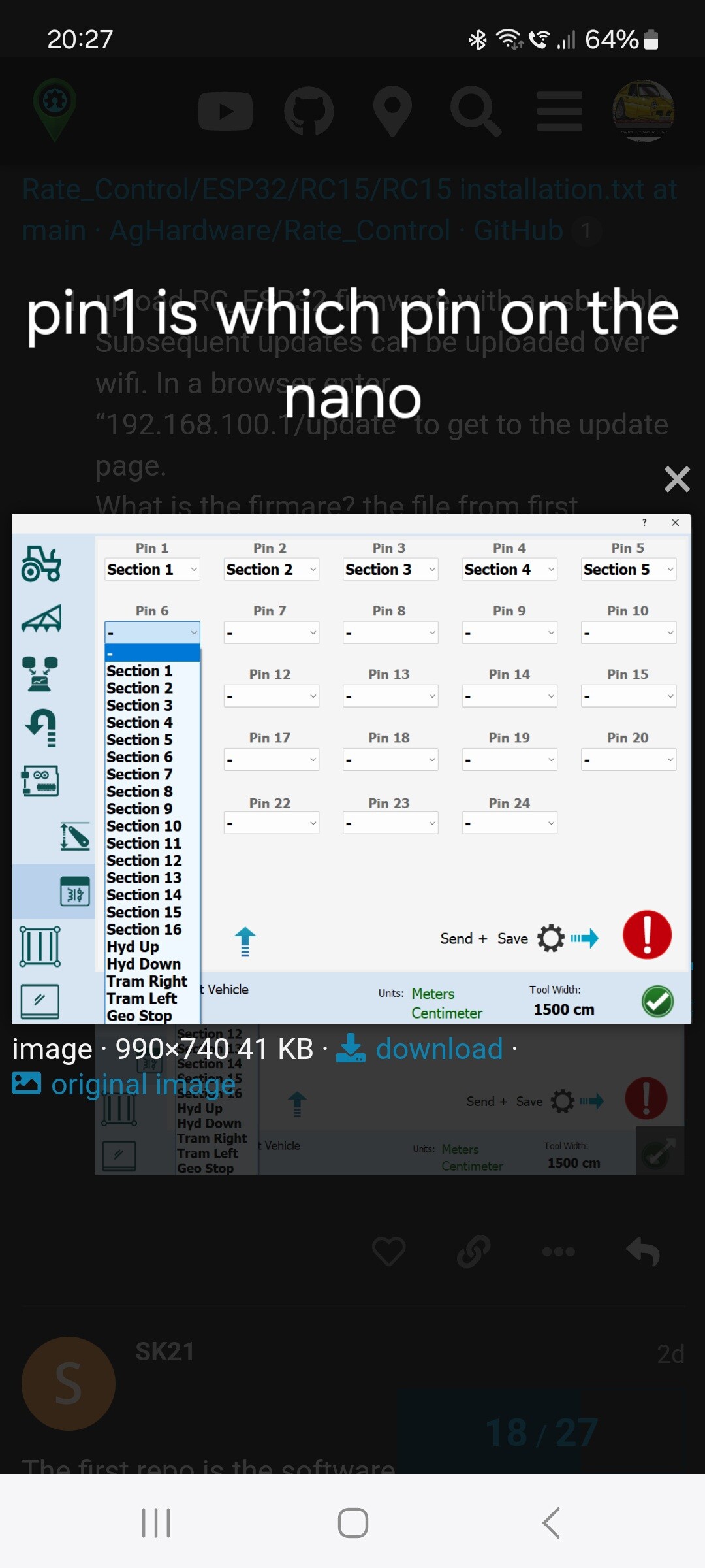
Is there a guide as to what pin on the nano corresponds to what pin to assign in the machine module setup page?
Pin 1 in the machine menu can allocate a certain section but what is pin 1 on the nano? Im using pins D4 to D13 and ive changed some coding and ive also allocated pin A0 and A1 so 12 sections and i can get 0v and 5v on all them pins by switching the spray on buttons.
Just need to allocate what pin does what.
Thanks
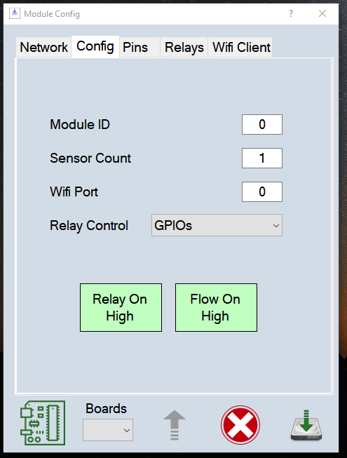
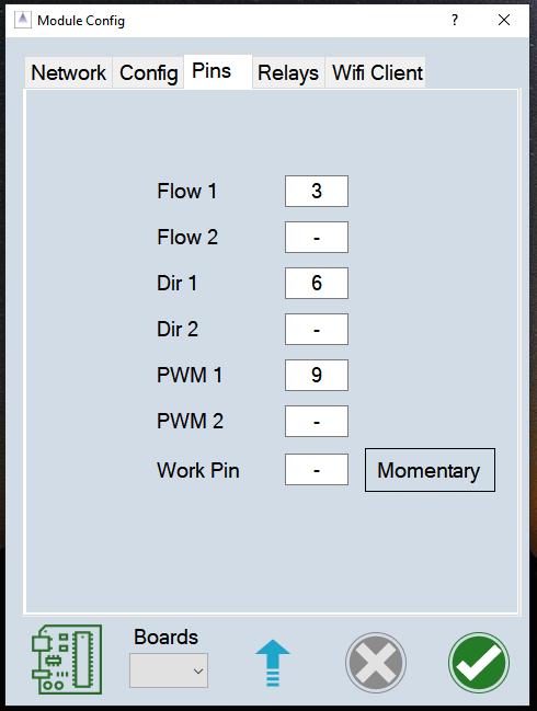
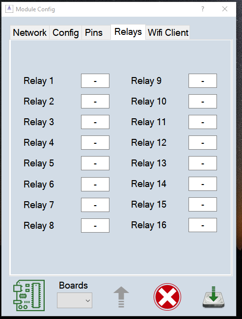
For the rate control app the module pin setup is in the app on the Module config page. Set the relay control type on the main config page. (Nano GPIOs or an IO expander) There is a page for the adjustment valve and for the relay pins.
Is that the extra rate control app? im using the machine module setup on the machine setup page im using usb from the nano to the tablet.
Its all working but unsure which of the nano D pins relates to the pin numbers in the setup page. Eg pin 1 is D5 on the nano
Maybe this page. Machine Board · AgHardware/Boards Wiki · GitHub
Pin 1 in AOG is the first Nano pin (whichever you used), the one controlled by bit 0 of the relayLo byte, probably D4 in your case. Are you using UDP or USB Nano? The UDP version has only a few pins available for section control. I think p9-p13 are use by the ethernet shield.
Im using the nano connected to the tablet via usb.
Originally i could only get 5v switchable output on pins D4 to D13 so i altered some coding in the software to use pins A0 and A1. I now now 12 usuable switchable 5v pins for my 12 row beet drill. I can turn these on and off by pressing the spray coverage button so all good.
I cant work out when i go to the setup page with the pins and all the drop down menu’s to assign the sections what does pin1 operate on the nano?once i know this i can then assign the sections to each pin. Do you mean pin1 would be D4 on the nano right through to pin12 being A1?
When i turn say 3 sections off on the screen it kills the voltage to 3 pins on the nano but they are in no particular order.
Which code are you using?
I don’t have time to look at the code right now but why don’t you set your sections, pin 1 to 12 as Section 1 to 12 in AOG and then in sim mode manually turn on each section 1-12 and see which output it is.
It looks like you have to configure your pins here
uint8_t pin[] = { 1,2,3,0,0,0,0,0,0,0,0,0,0,0,0,0,0,0,0,0,0,0,0,0 };
If you’re just doing sections continue the numbers up to your number of sections.
You likely need to expand this section for your A0 & A1 outputs
pinMode(13, OUTPUT);
And starting on this line you can see the order of Arduino pin numbers, 13 is the first section, I think you can reorder them as you wish and you’ll have to expand the section to include all your output pins
if (pin[0]) digitalWrite(13, relayState[pin[0]-1]);
I don’t know why pin 2 & 3 are excluded here.
This is exactly what i did.
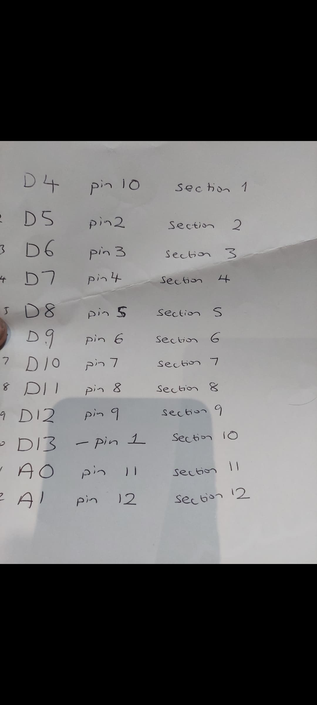
For anyone else interested this is the pins in machine module to the pins to the nano
Now that would have been handy when I setup my sections. Maybe should be in wiki?
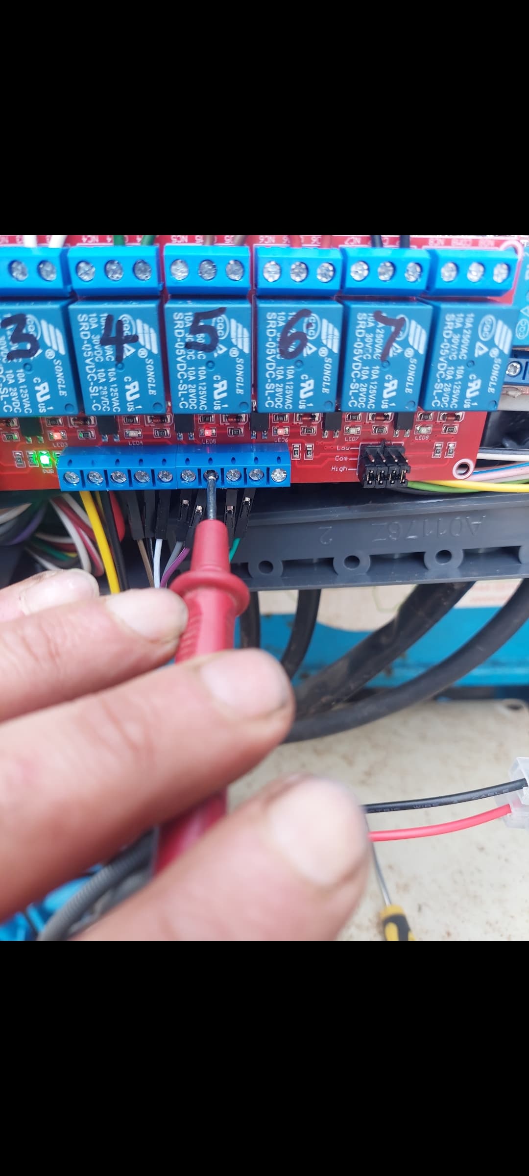
Im trying to setup section control on a beet drill. Currently have a 5v relay board that is powered by a 12v to 5v converter. The relay board lights up green.
Ive connected the nano to the relay board to the appropriate pins.
When every section is turned off all the pins im using from the nano read 0v.
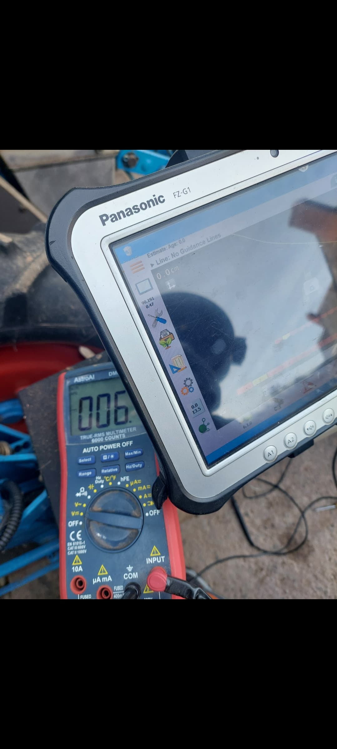
When i turn 1 section on that pin now reads 4.7v and that relay turns red light on. Problem i have is that by turning 1 on also powers up the other 5 relays, the lights are on very dim but the relay is trigged, i tested the pins on the nano that shoul
d read 0v when infact they actually read between 0.04v and 0.06v, this stray voltage is enough to trigger the other relays. Ive swapped the com high to com low and no difference . Ive invertered the relays but problem still exists but the opposite way. Ive tried a different nano and breakout board and tried a different usb cable but cant get the pins on the nano to read a dead 0v. Any ideas as its now driving me mad ![]() .
.
The one picture shows 4.6v on section 2 that is activated but also shows 0.06v on relay 5 and the leds are on very dim