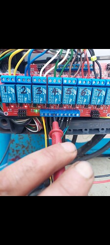
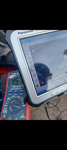
Will also add that when i test the nano in simulator mode with just the nano connected to the tablet i get the same result, cannot get a dead 0v unless every section is off
What hapens If you put 5v from converter to one relay?
Ive not tried that. The problem of stray voltages exist before i even connect to the relay board. The relay board must be very sensitive to a 0.06v and activates
Seems the internal pull down resistors are too weak. Try to add an external resistor of 10 K to pull down the pin. Pull-up and pull-down resistors on Arduino - ElectroSoftCloud
I have 2 nanos, ones a genuine one and one is a copy and they both do exactly the same.
I was hoping to do a 12 section control beet drill but having trouble even getting 6 sections going.
Im guessing id need a resistor on each pin as they all read a voltage above 0v. This is all starting to get a bit technical for me now ![]() but it would be good if i did succeed
but it would be good if i did succeed
I believe i might have resistors perhaps, how would i incorporate these into the nano/relay board
My suggestion goes on putting the resistor somewhere between all output pins and GND.
But I have also noticed that pull down resistors are normally on the input pins. Does the ino program define to use the internal pull down resistor on inputs? Arduino Pull-up Pull-down Resistor | Arduino FAQs
Do you possibly have it connected incorrectly? 0.06 should not turn on the relay board. When the arduino pin is set as output, it will either pull low to 0 or high to 5v, an extra pull down resistor only helps to hold down at boot up before the pin is set as output low.
Im powering the relay board itself with a 12v to 5v converter.
Even without the nano and breakout board connected to the relay board im getting these strange voltages when i turn 1 section on in simulator mode that pin reads 4.7v but then the other pins start to read a small voltage ranging from 0.04v to 0.07v ish. When every section is off every pin reads 0v then.
Im using the sketch from the zip files machine modules, arduino, usb v5
The lights on the relay that light up are very dim when this happens but testing the relay output confirms that it is actually switching
Currently only tried 6 sections so far on 1 relay board so im a bit reluctant to carry on with the other 6 until i can get this going
Maybe i have a coding issue perhaps
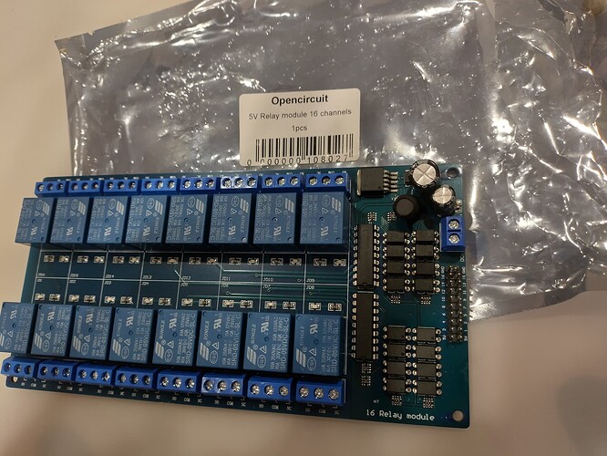
I went for 2 smaller ones as im a bit stuck for space to put them
What is the advantage of the 12v 5v one
Any links to that board
Is it possible to invert the relays and see if that works for you? Inverting the outputs on the nano too I guess and use input pull-up?
I tried inverting the relays in agopen and sent to module. The exact same thing happens but the opposite way around . With or without it connected to the nano. I did recall that one pin switches to 4.7v but when switch to off goes to 0v then starts to climb after a few seconds to 0.9v then drops again. (Cant recall which pin this was on the nano)
Is there any other sketches i could try perhaps ![]()
I have not tried it yet, but I think you can power it with 12v and power nano from relay module 5v pin.
Edit. I see you are using USB so no need for other power input for nano?
You did not specifically tell if you had all relays turned on from AOG at same time, and then off. Could you check what happen, when you turn all relays on, and then turn them off again from AOG, except one relay. Maybe the ino can keep a pin low, but first after it has benn active?
When i turn any section on via agopen all 6 lights come on the relays (1 strong light 5 dim lights)
When i turn each section off 1 at a time in agopen the relays still stays lite up right until you turn the very last section gets turned off then they all go out.
Ive done this countless times turning different ones off and leaving different ones on but as soon as i turn any 1 relay on (this always has the brightest light on) the other 5 light up dimmly . Makes no difference which order you turn them off in all 6 remain on until the very last one gets turned off then they all go off
What happens down stream of your relay module? Valves/solenoids?
Are you using the relays to make a positive supply or make a ground connection to your section?
Does this happen with both relay boards?
Ive not tried the 2nd relay board yet.
Originally it was a 12v relay board so i swapped it to a 5v relay board.
The relay output is operating electric motors. Just killing the power to each motor basically.
Ive not touched the wiring for this as we’ve had the section control running on a trimble system with field iq and it works. Idea behind converting it to agopen is to make it easier to put in and out of the tractor and hopefully be able to use some rtk.
Im pretty confident the wiring and relay board is good as i can replicate the problem even without the nano connected to the relay board by testing it with voltmetre in simulator mode.
Is there any other sketch i could try and its looking like a sketch/software problem perhaps
Maybe there is something in the sketch that is wrong as i uploaded the same sketch to both nanos and they both behave exactly the same.
You can’t really write a Sketch that will produce small stray voltages from digital pins
Im most concerned by the fact a .05v input energizes what’s supposed to be a 5V relay coil.


