I agree it must be super sensitive. I’ll try powering up the other relay board and see how that behaves.
Thinking about it the exact same thing happened when i 1st powered up the original 12v relay board. One light that got activated would be alot stronger than the others so i presumed the 12v board was too much for the nano to operate so i replaced it with a 5v board but now the problem has multiplied due to the lower voltage tolerances
You are certain the contacts are actually closed on the relay which isn’t being switched?
You are not just going off the lights on the relay board?
Do you have a link to the relay board data sheet?
Testing the relay output with voltmeter confirms that with s very dim red light on the relay is actually switching
I’ll try the 2nd board with no motor wires attached and see how that behaves next
You have to explain how you do this test. With no nano, meaning you put 5 v on the relay board input for relay 1 and then the other relays activate as well (with dimm diodes). Also if you can replicate problem without nano ,then it doesn’t matter which sketch is on the not connected nano.
Ive not tried that. Ive only tested both relay board and nano when both connected and only tested nano when not connected. Not actually tested relay boardby itself so will try that ![]()
About wiring. Do you have ALL GND connected at same GND?
Im not sure on the output wiring to the motors, it was all working previously on the trimble system so ive left that alone. With digging into another electrical box on the drill i couldnt tell you where they are grounded
Ive got the power direct from battery to a 12v to 5v converter thats powering the board.
I’ll try my other board connected up but leaving the motor wires off and see what happens.
Thanks so much for help and suggestions so far its much appreciated. Im just starting to get a bit stressed as the drill will be needed next week.
I believe the important modules here are nano module and relay module, and 12 to 5v power module, which obviously would have same GND as relay module
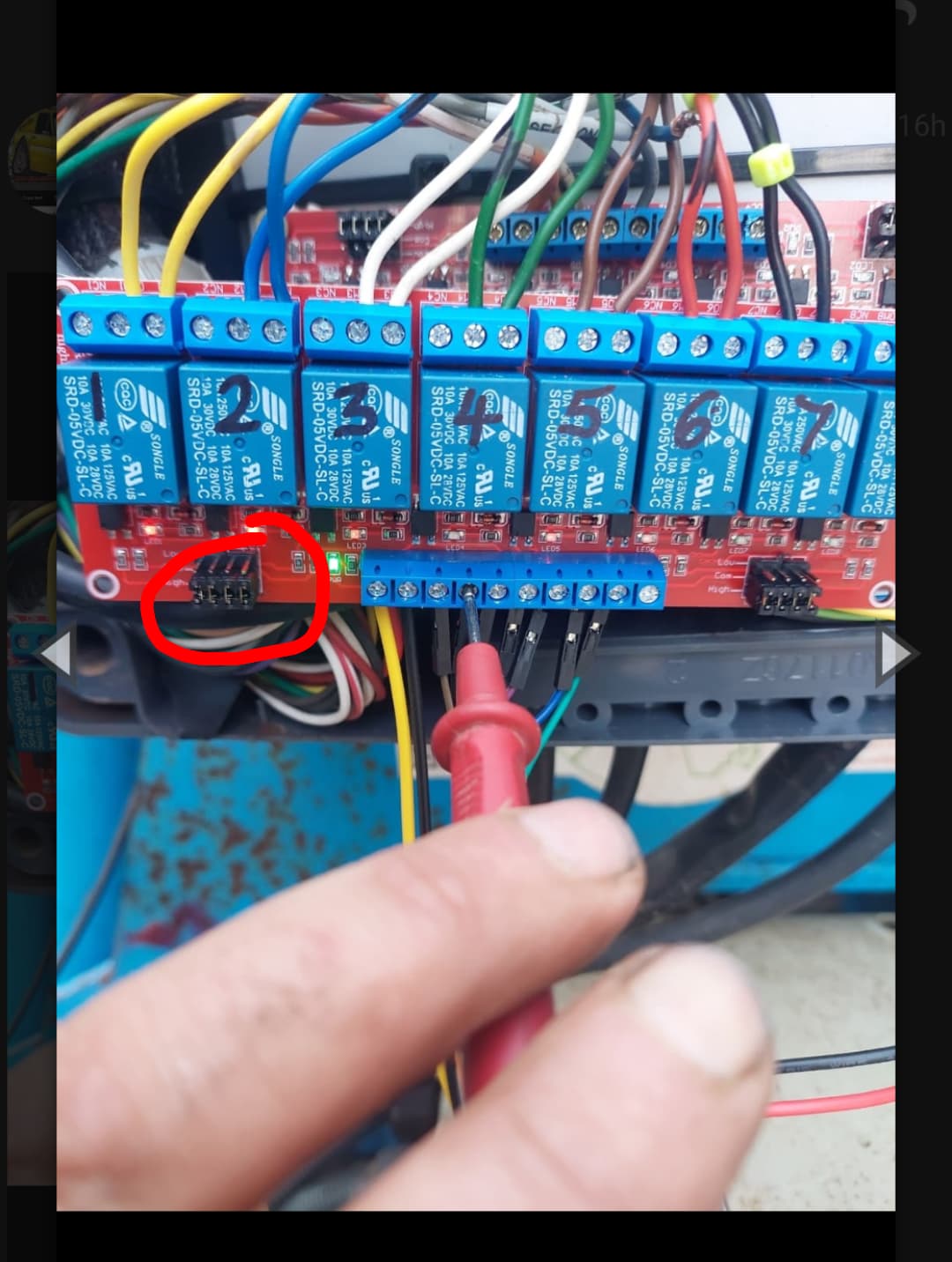
Those are used to select low or high level triggering.
When i tried swapping them it didn’t seem to do anything different
Them, as the PCB jumpers or?
Make sure your code is setting all outputs as pinMode: OUTPUT. By default they start as input and when you digitalWrite to a pin that’s set as input you enable and disable the pull-up resistor.
I have a few relay boards that are all a little different in how they get powered and connected. These relay boards generally have transistors to trigger optocouplers which do the relay coil switching so it doesn’t need much power from the Nano to switch the relay coils.
Yes them little jumpers but nothing changed for me.
Ive been into the code as there was only 10 output pins. I changed the use of A0 and A1 to output aswell.
A1 switches from 0v to 4.6v
A0 switches to 4.6v but then rests at 0.9 to 1v
Well nothing happens before you do something with the input pin. When jumper is set to high( as in picture) relay will activate when you put 5v at a input. . If set to low, same relay will activate when you put pin to GND. You can check without vires from nano connected, just use the 5v and GND supplying the board, as source for an input.
Can you put the data sheet up for the relay board
This is the board i bought off amazon . No idea on the data sheet im afraid
Going back to order RC15 on JLCPCB I had such an issue
Is that OK?
Should I proceed or this is different part?
Regards
Jacek
C7013144 is correct.
Right ive got an update.
Ive used my 2nd 5v relay board and powered it up and its working.
I can now switch 8 sections on and off in any order and all is good.
Ive still got a slight problem but definitely making progress.
There are only 10 switchable pins on the nano D4 to D13 all of these switch 0v to 4.6v from agopen, ive tested each of these separately and all work so i now have 10 switchable sections.
Ive altered the code in v5 usb machine modules to also use pins A0 and A1 to give me 12 sections.
Ive now got 4.6v on pins A0 and A1 and both go to 0v when i turn agopen sections off. The trouble is even though im testing 4.6v on pins A0 and A1 they won’t actually activate the relays. Tested numerous times and checked wiring and its definitely outputting 4.6v. Tried activating different relays but still no joy.
Have i done something wrong in the code perhaps.
Is there an easier way of using maybe pins D3 and D4 without any code change
Certainly made some progress now and starting to feel better about it
Edit.
Just tried the 2nd nano and again everything works 10 sections switching perfectly.
Also pins A0 and A1 also outputting 4.6v and again not actually switching the relays