First timer here and nearly got it working, but not quite. Am hoping it is something obvious…Need help to get from Yellow Tractor icon to Green incon…so near yet so far.
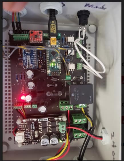
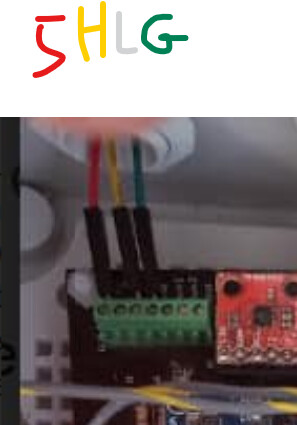
I have assembled a V2 PCB Steer Board, with Nano, Cytron, 24V Phidget DC motor, Range Rover WAS, latching switch on the “Steer” input (works to toggle from Red icon to Yellow) F9P for Rover (works well), Microsoft Surface Go2. Steer board receives power both from USB and fused 12V line. Nano running “Autosteer USB v5 0.ino.” WAS wires hooked to 5V, Grnd and signal now attached to High(older picture shown here shows signal to low)
Have checked and octocoupler not in backwards. New Nano installed and working. WAS gives changing voltage on signal wire when WAS moved. So what am I missing?
Hopefully this will turn out to be just another “I didn’t know that!” fix.
Yes created a field but haven’t set a path…trying to get WAS working and setup first. Currently have whole setup out of tractor and in office to complete.
I’m not familiar with range Rover WAS. Have you confirmed the +, -, and signal pins? Did you accidentally put power to wrong pins? Was closer while connected to board. Signal voltage should range from close to 0V - close to 5V (or supply voltage). Try another WAS.
The Range Rover “WAS” is actually used as a seat height sensor in Range Rovers but many have repurposed it for a WAS in Agopengps applications. Will get another WAS as I am pretty sure I have powered the pins incorrectly in the past. I take it that powering the wrong pin could fry the WAS? Good to know the expected range of signal values. Thanks.
To show my true lack of knowledge of the software…While waiting for my new WAS, can I continue to set up the system and run it like a glorified light bar? Can I run it and see my passes on the screen? An thing need to be different from what the manual and steering basics videos show? Please advise…Thanks
Working on getting base station talking with the Rover today.
Yes. Everything is the same, just your autosteer won’t work and your wheel angle sensor will show a tight turn. You’ll have the lightbar at the top of the screen and the offline distance at the top of the screen to guide you. The last release has the Sven arrow to guide you as well. Coverage logging works as normal to see your previous passes.
My steering valve on a tractor has issues and I hand steered many hours this fall, using AOG as a lightbar.
Most of us lack knowledge. Don’t worry about that. Learning is what this is all about. I am strong in electrical and weak in programming. I have burnt up many sensors in my electrical career. Sometimes reverse polarity, or power to signal wire is unforgiving. Good luck and don’t give up. I have 4 successful auto steer systems I like better than the high dollar ones.
Kevin, thanks for the encouraging words. I am blessed/cursed with what my mom called sticktoitiveness…Our family motto is “How hard could it be?”…that said, this project is really challenging for the electrically challenged such as I am…lol…Stay tuned for more questions!
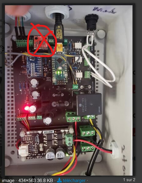
Bribric, good eye noticing the incorrect signal wire placement…it i s an older picture and I now use
high port…
I am a complete newbie with all this electrical component realm, and most of my build is completely “Monkey see, Monkey do” logic. I only have gotten this far because of the generosity of you smart guys making Youtube videos I can start to learn from…lol.
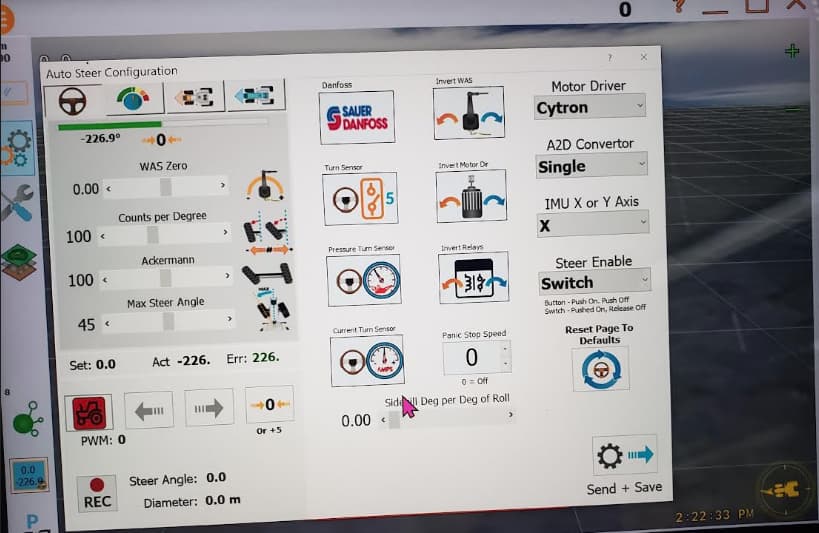
Just to be clear, when you say the MMA board is not needed with V5, you are referring to V5 software, which I am using on my V2 board. I chose a V2 board to build because of Jim Duggan’s and Darren Lobb’s videos (remember Monkey see, Monkey do). So if I remove MMA all is good or do I have to jumper wire something?
You can jumper wire in the BNO085 if you have one in place of the MMA. The BNO is a much better performing IMU which is why it replaced the MMA. I don’t believe it is plug and play so you will probably have to use jumpers to get the wiring correct.
I also am a beginner who has muddled my way through this project but it has been very satisfying to see the project come to life and to get to use it. I also owe many thanks to the brilliant people on the discourse. Just keep after it, it can be confusing at times but it can be done!
gpierce720…At this stage I don’t care about better…I just want to get the darn thing showing my tractor driving around the field…better is for later…If it will work with an MMA and V5 software on a V2 board, it is just fine for this old farmer that has lived without any GPS guidance in a tractor for 50 years… lol
Thanks for taking the time to respond…I truly need the help!