Image links don’t work.
Didn’t test with seed drill I want to have straight line before seeding when seeding starts that is 2 man job and I cant stop to test and have bad lines, if it oscillates on seeding then it will be mind numbing to follow that line for spraying and cultivation better to seed manually with not so strait line then that.
Will try to rebuild WAS my wheels 0 is 115mm full stroke is 195mm so one side is 90mm, to mount sensor to read 0 when wheels are strait or mount it to read 0 on 100mm. @alexandr do you have same problem?
I think that both options have ackerman but mount on 100mm will leave full range of sensor but WAS 0 in AOG will be off or WAS have better resolution closer to 2.5v ? then on one side will have less resolution but when wheels are strait WAS will sit close to 2.5v.
The sensor really only reads about 90degrees, it sometimes is tough to take advantage of the full range, or from overshooting the range of the sensor.
I think @alexandr last image is a very smart way of installing the was in this application. The front end of that machine is quite busy, tons of angles, quite challenging.
2 Likes
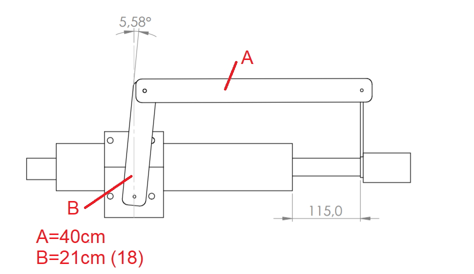
When cylinder is closed WAS needs to read 38deg while when it extended only about 20deg. I think that I can get 30cm for A rod to fit there.
Can AOG compensate for uneven cylinder extension ? or should I leave it as is it. Now I understand why people want WAS less autosteer 
1 Like
Yes that is the percentage you set in AOG in the Ackermann setting.
3 Likes
Yes the ackermann setting will even things out. Once you have centered your WAS, You turn hard right first to set counts per degree, then when you turn hard left you use ackermann to make left degrees equal right degrees. Assuming your tractor tires turn the same both directions.
WAS seems like a big task, but after you get your first one dialed in It is worth it. WAS makes the whole steer system very stable. No wiggling, and hopefully soon no wiggling for you as well.
2 Likes
If this means low Max at 115, then reduce to 35.
There was an excel file that explained how low max worked, in a post earlier, but the link is too old.
Use the seed drill on hard ground without using seeds. do some kind of demo. go and come back from the same line and you will see the margin of deviation. When there is hard ground, the soil cannot close the line, so the deviation seems clearer because it remains in the form of a line.
1 Like
What if it steer 5 deg more to one side ? With phone app its no so accurate but it seams that it is more to one side will test again.
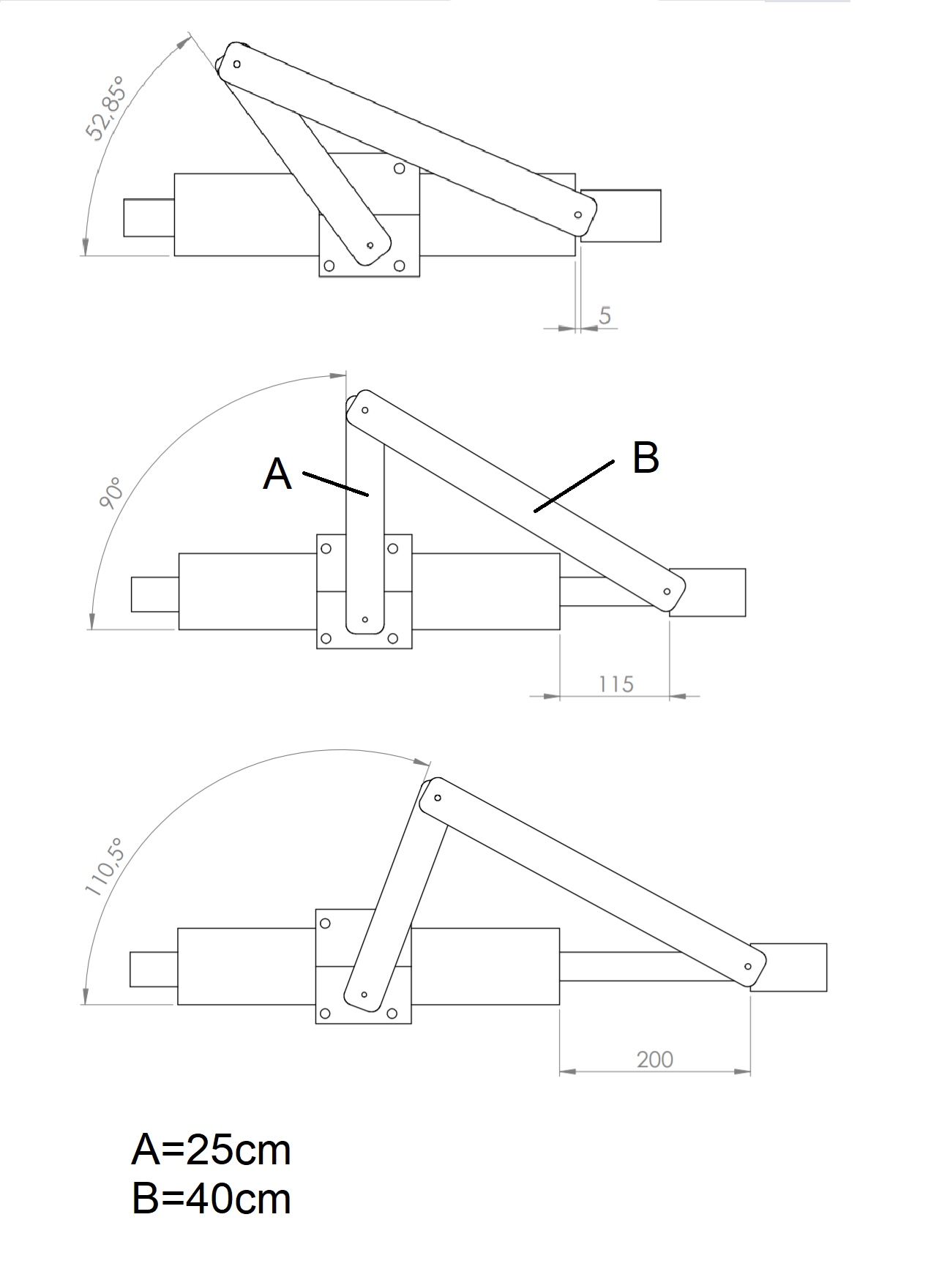
Your drawing induces extra Ackermann at the left side /at 52. degrees side. Make a paper experiment, where you have middle of sensor around straight up.
More about low max. Nothing can happen between your min pwm of 55 and low max at 115, but when the error makes AOG output 116 then finally you get that. This Will make your tractor drive oscillating.
I will lower minimum and low back to 30 and up to from there.
In that drawing it is ment for sensor be up when wheels are strait. Thats question will it be better to be in middle of cylinder but sensor will not be strait up when wheels are strait.
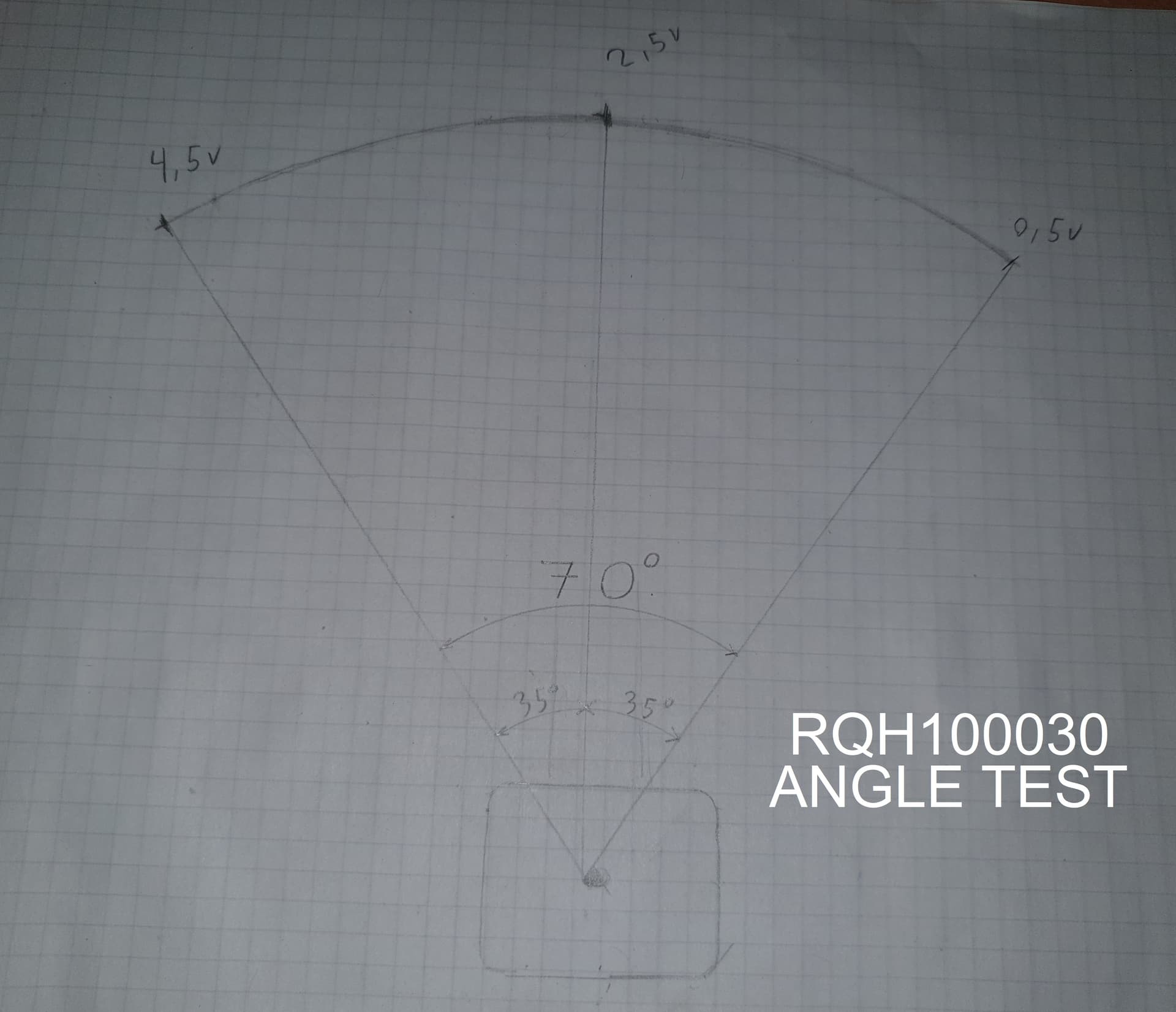
I think the linkage at sensor is too long.You use a small sensor angle range (approximately from the picture and posts +/- 12 degrees around WAS zero) that AG “expands” to +/- 35 degrees. Plus, I don’t know what it’s like with the Land Rover sensor, but with Mercedes it’s +/- 45 degrees around the center position. Mounted like this for entire right position of the wheels, the sensor would give 4.5V. Can you measure the voltage at the sensor output for full left, straight and full right?
PS.
For my sensor it is currently :
0.5V full left,
1.77V in the center position (straight )
3.81V full right
1 Like
Are you referring to my existing WAS it uses almost full range because steer rod moves alot if used shorter link it will go out of range.
In this new configuration it have to move 200mm i think that range of sensor is ±30 to 35 deg when i mesured link I try to use full range to sensor be at 30 deg at full turn. Maybe its not install WAS problem as it used full range. Only problem can be that steer rod moves in bouth directions horizontal. But that effect should be minimised because is close to center of steer rod.
So your WAS is not strait (2.5v) when wheels are strait ?
Yes in version 5 and up you can zero the WAS from almost any center value. In AOG ver 4 center value must be closer to zero for easy zeroing.
2 Likes
If one direction actually steers more degrees than the other, set it up in steer settings so both sides are equal to the smaller steering side to start.
But the ackermann setting will clear up any differences, cpd sets right side, ackermann sets left.
2 Likes
Its ±35deg from 4.5v to 0.5v
[WAS sensor RQH100030 “land rover model”]
2 Likes
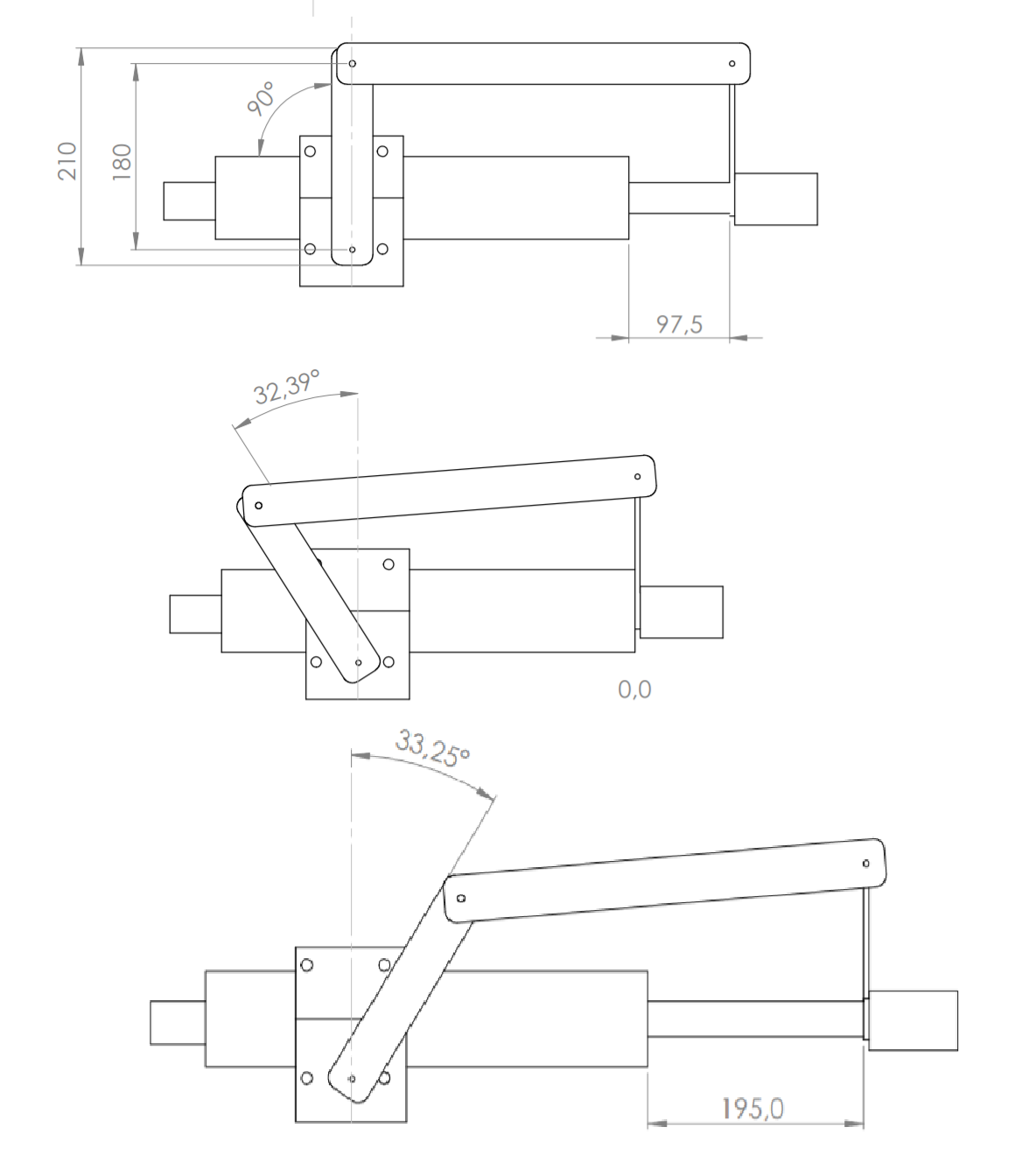
With 180mm between centers of rotation pins it gets close to full range of sensor.
But WAS 0 needs to be set to 6~deg in AOG (with steer strait method).
there is about 27deg when steering to right and 38deg to left, but full range of sensor is used this way and ackerman should compensate for this.
3 Likes
If we place the imu sensor under the tractor as much as possible, what do you think would be the level of accuracy and improvement? Currently the GPS receiver and sensor are at the same level on my tractor. bno08+ plans to place it in the middle of the tractor, under the cab.
Much better gain would be lowering antenna to hood, how much lower is antenna there is less error to correct. But there can some improvement lower it is there is less sideways movement.
Good test is antenna on hood and IMU lowest point that you can reasonably install with IMU module that is stand alone from PCB you can try many places and heights.
There are 5 modes that BNO can have and there this https://xdevs.com/doc/CEVA/BNO080-BNO085-Sesnor-Calibration-Procedure.pdf
Unless you have cab suspension, IMU location does not matter. Front, back, roof, floor, console the math is the same.
Somewhere close to level with the rear axle, inline with direction of travel, securely mounted and weatherproof.
1 Like
https://youtube.com/shorts/nCGYNJqIUek?feature=share
The GPS receiver is in the nose. The box appears in the video. bno08+ In its own mini aluminum case. in the middle of the back hanger. I put it right next to the box. at a point without a magnetic field. Suitable for your suggestions. In this case, I’ve already done the correct positioning that I need to do. The only one I haven’t tried is the minimal filter experience. Let me try again by reducing the filter of the sensor to minimum 20 band. fewer filters