Throttle Position Sensor as WAS

I was able to buy some cheap TPS sensor from amazon.fr (2.89EUR a piece) https://www.amazon.fr/dp/B08P2LYRMZ/
Part number:

Bp2y18911a / 89452-10040/89452-02020

I also found corresponding connectors on aliexpress: 1 Set 3 Pin 90980 11261 Auto Waterdichte Sensor Plug 7283 1133 10 Voor Toyota 1JZ Tps connector Gasklepsensor Stekker|Connectoren| - AliExpress Part number:

3 Pin 90980-11261 | 7283-1133 | 7283-1133-10 Grey | 7283-1133-30 Black

If this works then for 5 EUR I have the WAS + connector.

Ignore this, see the solution with pictures about the inside + connections.

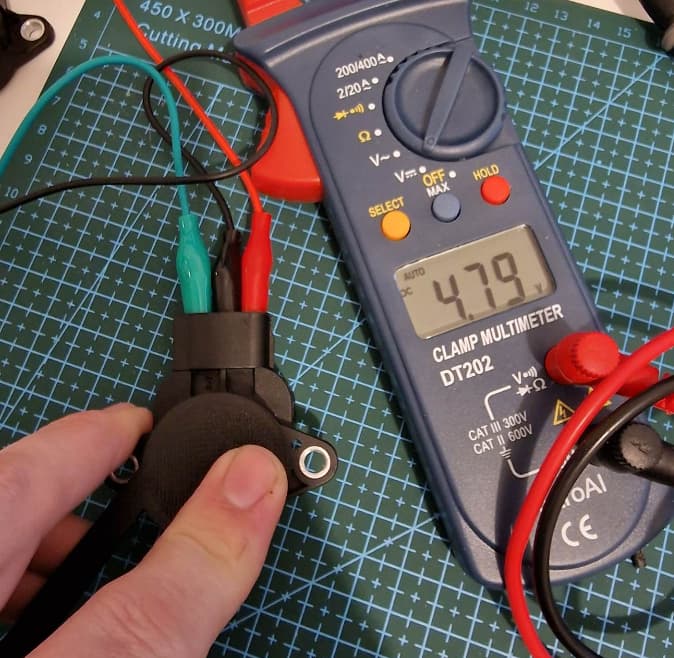
Unfortunately based on my test this takes 12V as an input (starts to produce a 0-5V signal when voltage reaches 9V) the universal V2 PCB uses 5V as the WAS. If I increase the voltage the signal starts to fluctuate slightly, this means if my voltage is not stable the WAS will not be stable either. (I'm foreshadowing here.)
The board has a 12V output that seems to be stabilized. (Should I have the Cytron receive 12V directly without the capacitors for the motor? Would that help stabilizing the board voltage?)

Another question is where to put the signal that comes out?
Does this make sense:
WAS_H -> Signal from my WAS
WAS_L -> ground of my WAS
12v_board -> power to my WAS
1 Like

We could assume it is like a Honeywell high voltage WAS. Works on anything between 10 and 30 v. Because it has a built-in 5 v regulaor.
So yes 12v from board
Signal to high
Gnd just to gnd

Actually the pcbv2 does NOT have regulated 12 v
(The small 12 v out is just a little less than battery because of loss passing the diode)

1 Like

Update: I designed an arm for this TPS sensor (arm seems to go either way on the sensor and the mounting screws act like a limiter)


Unfortunately I’m weeks away seeing this working on a tractor :slight_smile:
WAS Fusion 360_with_STL.zip (312.6 KB)

@Jhmach (sorry for pinging directly!) do you see any problem running a WAS that takes 12V in and produces 0-5V out with your new board? It should be 12V out + ground + signal back on WAS_H, right?)

I don’t guess it would be a problem, except there won’t be a dedicated power for WAS 12v. You would just have to test it and see. You are banking on a 12v sensor to never output over 5v. If it does the ads goes poof.

1 Like

Initially I connected the +/- on the outside (don’t do that…)

After disassembling (I let the smoke out first :D) it’s really not that complicated:

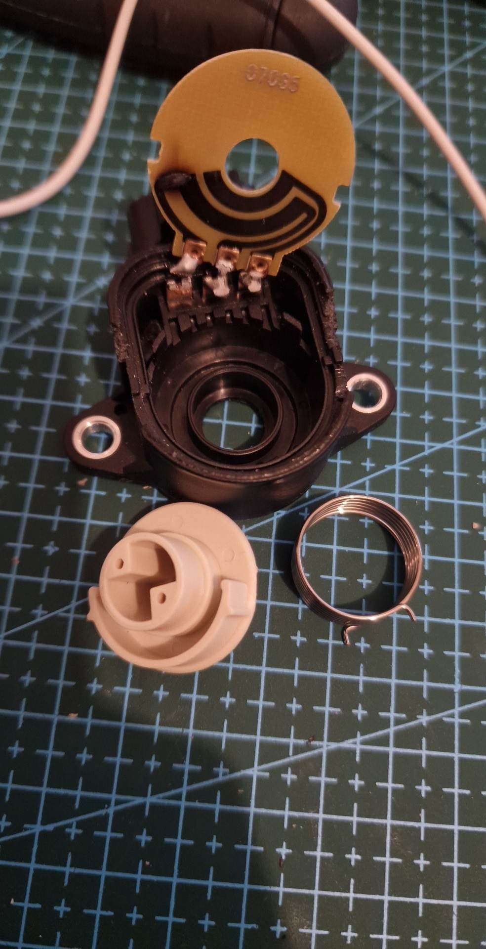
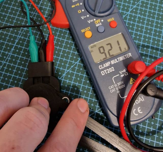
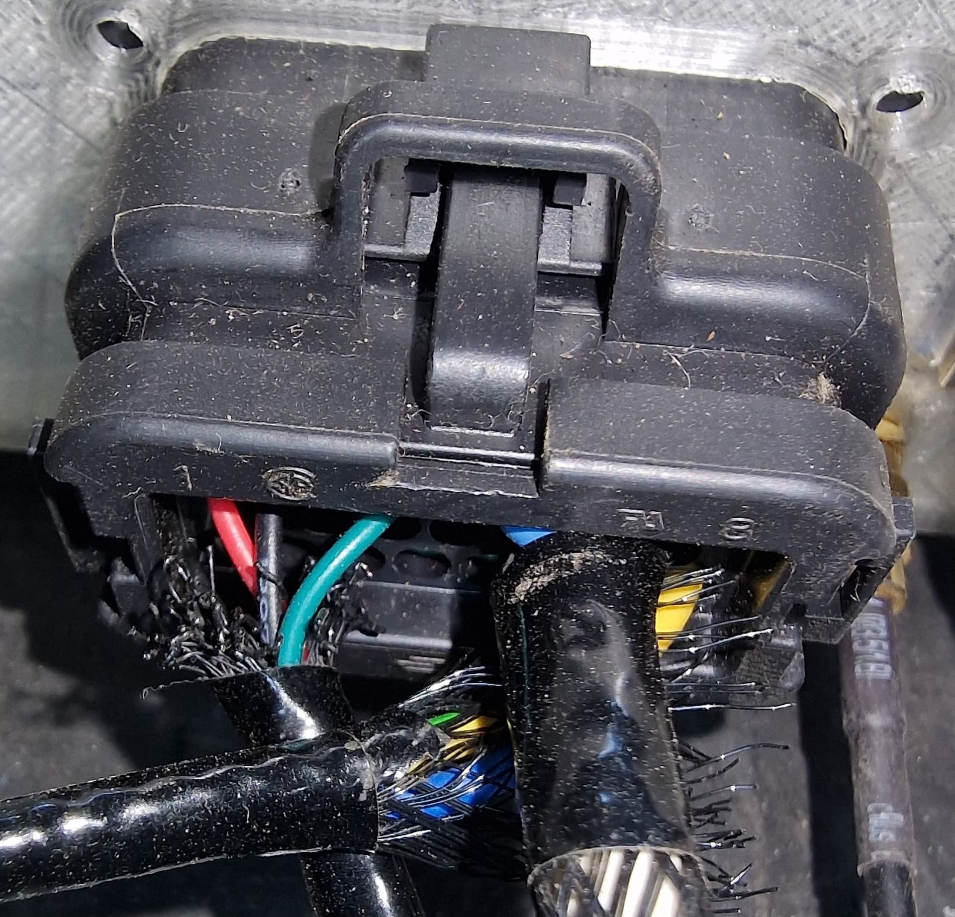
Basically the left pin and middle pin that is constantly connected you can measure 5k ohm across.
If I take signal from the right most pin (upper circuit) then it changes nicely between 0 and 5V.

So pinout is as you can see here:


After burning one of it and disassembling it makes sense why is this so cheap. (Hopefully it will last as well…)

2 Likes

You have to connect its output to WAS_H pin:
image
And choose differential here:
image

Viva la resistance:

Resting:
Red → Green 3.6k
Red → Black 3.45k
Green → Black 0.3k

all the way to the other end:
Red → Green 0.170k
Red → Black 3.45k
Green → Black 3.6k

Installation credit goes to my little brother :slight_smile: (I’m doing much better with google than the drill :smiley: )

We’ll wash the tractor later this week but this shouldn’t really receive any water here.

We ended up using a longer arm (I’ll upload the STL later…)

And the 2nd batch of sensors needs the “pin”/shaft rotated by 90 degrees.

I strongly suggest to buy 2 female + 1 male → you can add an extra connection to the CAB just in case it has to be removed.

Sensor itself: https://www.aliexpress.com/item/1005004979692332.html?spm=a2g0o.order_list.order_list_main.65.2f771802YOYqS1


3D printed stuff:

WAS Assembly stl_step_f3d.zip (753.0 KB)
Update the new TPS sensor needs a 45 degree:
WAS Assembly stl 45degrees.zip (153.7 KB)

  1. month update:
    1 died after 2 weeks… Other 4 survived so far.
  2. month we’ll start with 7 tractors, so fingers crossed.

10th tractor is up and running and got no more issues. prep work for planting is starting just now :slight_smile:

one of the tractors passed 500 hours, no problems with steer sensor

1 Like

Will this sensor work on 5v?

Yes it will. 40+ works happily, although it doesn’t appreciate heavy rain.

This week we tried another sensor and it seems to be a better fit as its IP69 rated:

1 Like