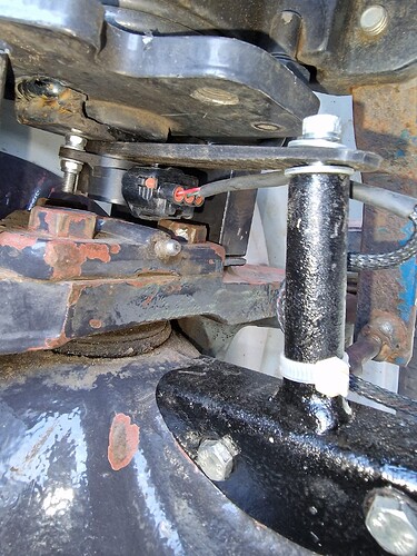
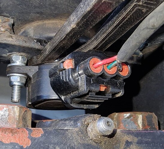
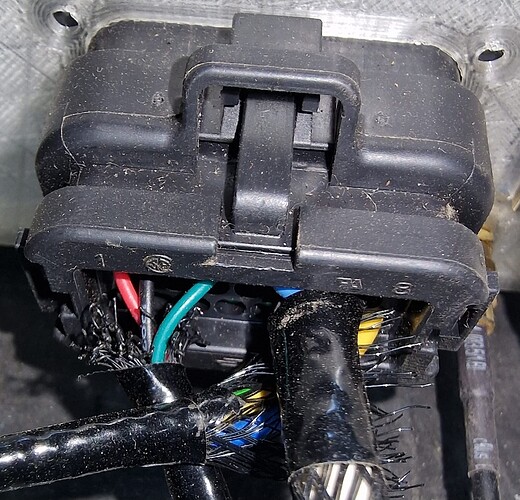
If this works then for 5 EUR I have the WAS + connector.
Ignore this, see the solution with pictures about the inside + connections.
Unfortunately based on my test this takes 12V as an input (starts to produce a 0-5V signal when voltage reaches 9V) the universal V2 PCB uses 5V as the WAS. If I increase the voltage the signal starts to fluctuate slightly, this means if my voltage is not stable the WAS will not be stable either. (I'm foreshadowing here.)
The board has a 12V output that seems to be stabilized. (Should I have the Cytron receive 12V directly without the capacitors for the motor? Would that help stabilizing the board voltage?)
Another question is where to put the signal that comes out?
Does this make sense:
WAS_H -> Signal from my WAS
WAS_L -> ground of my WAS
12v_board -> power to my WAS
We could assume it is like a Honeywell high voltage WAS. Works on anything between 10 and 30 v. Because it has a built-in 5 v regulaor.
So yes 12v from board
Signal to high
Gnd just to gnd
Actually the pcbv2 does NOT have regulated 12 v
(The small 12 v out is just a little less than battery because of loss passing the diode)
@Jhmach (sorry for pinging directly!) do you see any problem running a WAS that takes 12V in and produces 0-5V out with your new board? It should be 12V out + ground + signal back on WAS_H, right?)
I donāt guess it would be a problem, except there wonāt be a dedicated power for WAS 12v. You would just have to test it and see. You are banking on a 12v sensor to never output over 5v. If it does the ads goes poof.
Basically the left pin and middle pin that is constantly connected you can measure 5k ohm across.
If I take signal from the right most pin (upper circuit) then it changes nicely between 0 and 5V.