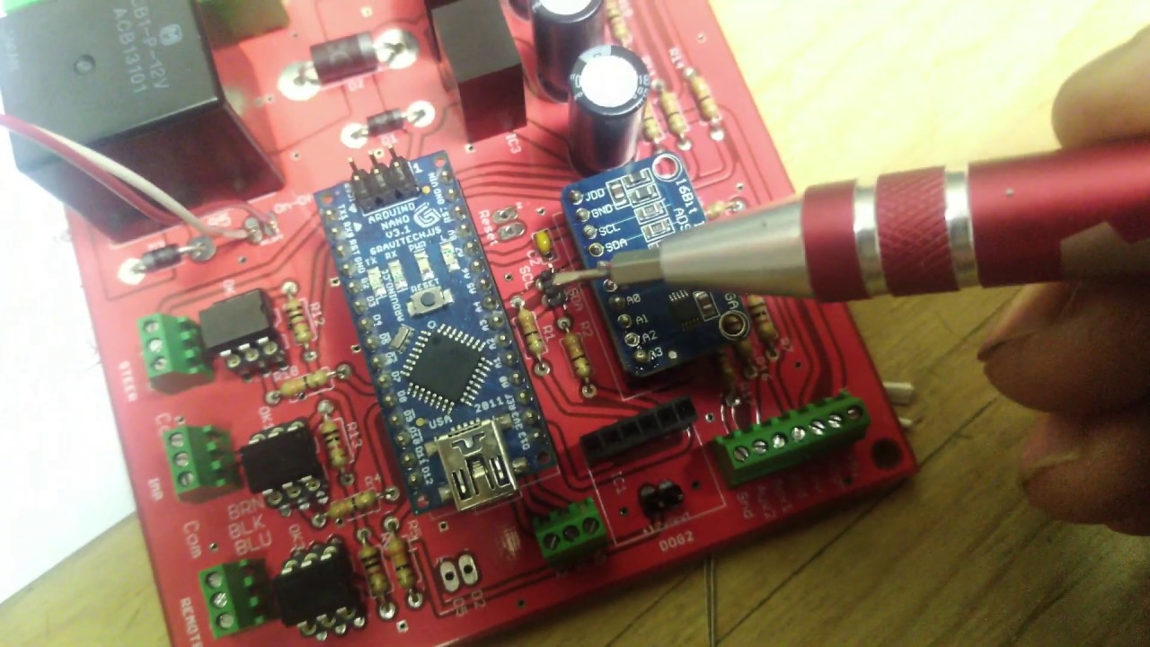
Video on what I learned assembling a PCB for the first time.
Very good video, thanks for posting. Please continue posting as you hook external components. This really helps this newbie.
Yes this is fantastic and is extremely helpful. I would echo OhioFarmer64s request that you post as you continue putting together external components!
Good video, funnily enough, I filmed putting mine together last night also for the same reason, seems you beat me to it though!
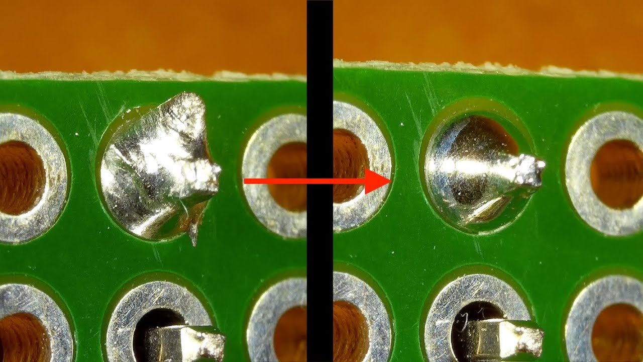
For proper soldering need 3-4 second for thermal transfer, not to long because will damage PCB , to short , not enough temperature make cold solder joint and bad contact.
Good info, thanks. Appears I’ll have to do a video on me repairing cold solder joints ![]() Soldering is not my strong suit.
Soldering is not my strong suit.
It’s not too late to post. Apparently mine is full of cold solder joints.
Good video though ![]() all you need to do is reheat because you used solder with flux.
all you need to do is reheat because you used solder with flux.
The problem is that you only heated ½ a second where you should have heated 3 maybe 5 sec. to make the solder point nice and shiny (must not look like a grey ball)
I is a new and clean board and it will be ok soldering with solder having a flux core.
But yes extra flux could make it even better, especially when reheating.
5 sec heating would be max if soldering nano and optocouplers directly to board, the other components are not that sensitive.
Yours PCB are top quality. For amateur soldering 0.5mm like Fluitin 1532 Sn62/Pb36/Ag2
low melting point, easy soldering.
For soldering wire with no Pb , something like Sn99/Cu1 , high melting point , not easy soldering.
When solder to pull on opposite side of PCB , that is OK.
What solder were you using, Wilber? I’ve had good luck for an amateur with the 60/40 stuff (similar to what grabik recommended). There’s absolutely nothing wrong with lead-based solder and I think most hobbyists should be using it over the silver based stuff. I’ve also found that smaller solder (0.8mm) can sometimes work better me than the bigger stuff.
I do very little soldering on pcb’s so I’m no expert. I tried to ensure the solder was flowing through the through holes and not just sitting on the underside. Seemed like a reasonable indication to me. I gave the joints about 2 seconds of pre heat, applied the solder then maybe a second before I removed the iron. Something like that anyway.

It’s the silver bearing, lead free, rosin core stuff.
A finger nail trimmer makes a good tool to trim the tails once board is soldered.
Ahh. Always a good idea to avoid the lead-free solder. It’s just not worth the trouble.
Even commercially soldered stuff can have problems with silver/tin solder. Cold joints, tin whiskers, etc.
Have a couple of PCB build questions.
- Ordered the PCB v2 from Gerber file but it doesn’t look exactly like the schematic because the one I ordered appears by the pic to have a big hole where the cyteon would sit but the schematic doesn’t. Thoughts
- If I plan to use a hydraulic valve to steer the tractor do I need a Cytron?
3.Any special mma8452 that I need to order, thought there was some talk of different bits? - What’s the best WAS for a 4wd?
- The 0 resistor at R8, talk looks like I just use a wire?
- What are the wirepad3,81/1,1 parts listed on the part list, don’t know what that is and can’t find them online.
- Have 2 parts show up on digikey list that aren’t on partlist or component list
Part 1212-1002-ND Conn IC Dip Socket 6 POS gold
Part A135912-ND Term BLK 7p side ent 2.54 mm PCB
Any ideas if I need these last 2 parts?
Other than that things went smoothly trying to find stuff and waiting for it to show now, sure hope I ordered the correct version of PCB via Gerber and have the correct schematic for the current build.
If you are a complete rookie like me, couple things I figured out, the parts list is a summary of what you need to order. The components list tells you where they go onto the PCBboard, same parts just different way of showing them. That took me awhile to understand ![]()
Thanks everyone
-
Yep the big space should be there for the Cytron motor driver. The schematic is a wiring diagram so not really a true layout.
-
If you plan to go hydraulic to the best of my knowledge you can still go with a Cytron, IBT-2 is another option.
3a) I believe you want the Spark Fun version as that’s the one that fits on the board. Take a look at @darrenjlobb 's video.
3b) best WAS for 4WD check with @Apm (Andrew Martin) there are also some install pictures on the combine forum. I don’t think that you really need a special one so long as you can make it use the full range of motion.
-
Yep a wire works. I used a clipped leg off a diode or resistor.
-
I’m not sure what that is. That’s found in the component list and not the parts list. I think you can ignore that.
-
Yep you’ll need Part 1212-1002ND That’s what the Opto-Isolators/couplers plug into. 3 of them I believe.
Part A135912-ND is a 7 position screw terminal and that’s where you can connect your WAS etc. You could replace these with pins if you wish.
Thanks for the reply. It’s all starting to make a little more sense now. I have everything ordered except a GPS, I ordered a tinkerforge imu brick 2 so probably going with a single GPS and not a dual that may be in the future. For a gps, could I use a spark fun Zed f9p board or is the arsdusimple rtk2b the way to go?
With the imu brick 2 going to computer by USB, and the nano as well as the GPS will they all work through a USB hub? Should I look at ethernet shield for the nano or does that change much? My thought was maybe 2 boxes in cab, 1 with the PCB and another box with the gps and a hub in it somewhere in cab that brick, gps and nano all plug into then one USB from that to laptop.
Sure you can use a spark fun f9p board although the Ardusimple board will be simpler, it works right out of the box no config necessary. They should work via a USB hub although I might suggest a powered hub. UDP is a bit more set up initially but once it’s up and running you can plug and unplug stuff without any issue. Personally I’ve only ever done the USB connections.
I don’t see any issues with 2 boxes.
Are there concerns with USB and starting sequences or unplugging and plugging? My thought was all things into a hub and then only thing getting unplugged would be 1 connection to laptop.
Thanks for your help

