Track tractors

Is there anyone else interested in getting AoG working on a two track tractor? I have a JD 8410T, 8320T & 9400T. They all currently have a very old AutoFarm 5001 (triple ant, gps only, Linux based) system that I’d love to replace with AoG. It steers by manipulating/overriding the tractor triple steering sensor stack, making the JD system think the user is turning the steering wheel.

The two main hurdles that I see to use AoG without mounting a motor:

  1. No WAS
  2. Interface with the steering sensors

#1 is already being worked on by people smarter then myself.
#2 I’ll have to do some research, see how they manipulate the steering wheel sensors’ signals. The installed AutoFarm system includes a harness that plugs in-between the tractor’s harness and the steering wheel sensors so they can monitor the steering wheel position and somehow manipulate the signals so that the tractor turns without causing safety errors/codes for the JD computer. I should be able to connect an oscilloscope to that added harness in the cab to monitor the signals.

If I’m the only one wanting to use AoG in these tractors, I might just mount a steering motor and use a steering wheel sensor signal for the WAS input.

Does it have a steering linkage underneath like a swather? Like an arm to a proportioning valve for steering or a gear that turns less than 360 degrees. Or is it all electronic?

WASless does sound ideal for this setup.

It’s all electronic. The computer reads the three sensors (redundancy) and controls the dedicated steering pump.

Does the steeringwheel point everytime when going straight in the same direction? If so, just add decoder to the wheel and it will determine the steer angle.

It does anyways point the same direction. As I mentioned before, if I use a friction drive motor to turn the steering wheel, then I’ll just use one of the existing steering wheel sensors as a WAS. The difficulty is if I try steering electronically, then I’ll need to use a WAS-less version of AoG.

Hi M_elias, Have you had any luck steering these tractors? I am new to this and have a range of 2 track tractors, but am interested in steering a 9530t at the moment.

Sorry. No progress yet.

Today I took the time to connect a volt meter and an oscilloscope to our 8302T steering sensors. I’ll use the connector & pin labels from this JD computer (SSU) diagram as reference.
Manuals - RW66957-UN_ SSU Wiring Diagram __ Service ADVISOR™.pdf (652.6 KB)

Connector X49 is where my old Autofarm connects in between, and it can manipulate the signals to steer the tractor electronically. I’m hoping to do the same with AoG.

The three sensors each have their own:
4.77V reference wire (W36 - pin A on each sensor)
signal wire (W36 - pin B on each sensor)
GND wire (W36 - pin C on each sensor)

The 4.77V references all seem common to each other, as well as the GNDs.

The Top (R16) and Middle (R17) steering wheel position senors match each other’s left/right polarity but the Bottom (R18) sensor is inverted from the other two (you’ll see in the numbers below). So there’s some redundancy and error checking in this design?

I’m hoping someone who knows this system can shed some light on what exactly JD is doing, I’m curious how exact the signal needs to be mimicked and how to override the steering wheel sensors with an analog signal from AoG. I’m thinking of trying to use a DAC like the single channel MCP4725 or the quad channel MCP4728 or something like a triple POT stack like the factory JD sensor stack to control with a servo or motor. I think a solid state system like the DACs would be best.

I’m wondering if the steering signal into the SSU needs to be switched between the factory steering sensors and my AoG analog signals or if I can leave the factory sensors connected and just manipulate the signals up or down. Maybe even just using a PWM output instead of a DAC? If I want AoG to turn autosteer off when I manually turn the steering wheel then I probably have to read the steering sensors with a ADC and output that to the DAC in manual steering mode, then in autosteer set the DAC accordingly to AoG’s commanded steer angle and if the ADC changes too much turn off autosteer and pass through the steering sensor signals again.

For now I’d like to start simple and only pull the steering signals up/down to control via AoG. This probably won’t allow for nice automatic headland turns but it sounds the simplest.

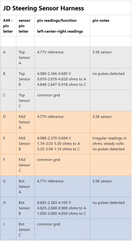
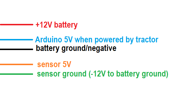
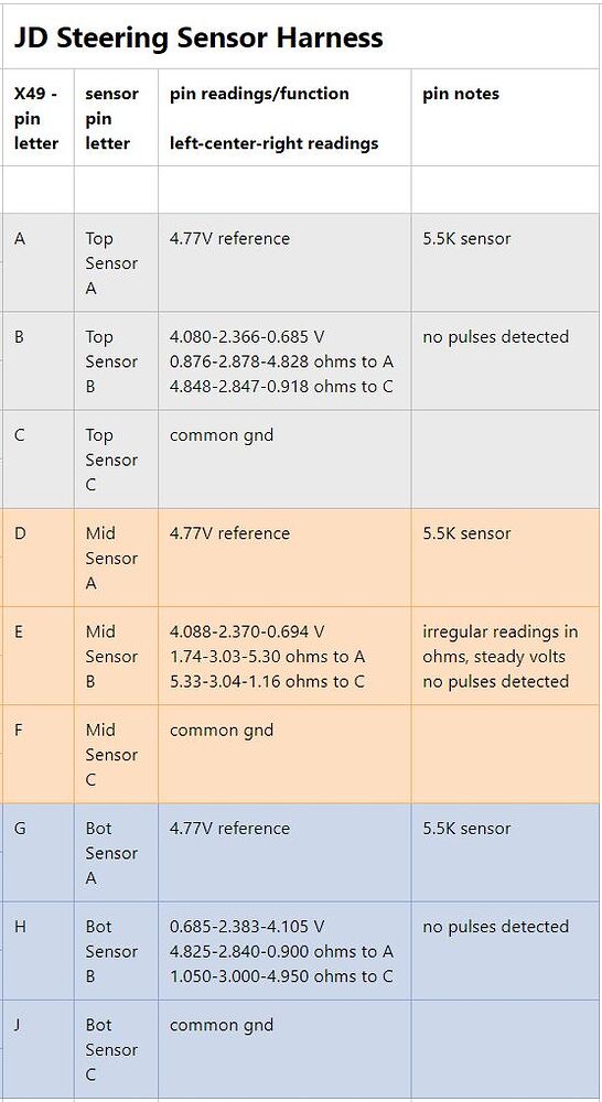
Today I connected two MCP4725 DACs to our 8320T. The two steering wheel sensors that move in tandem I connected together to one DAC output and the 3rd inverted sensor I connected to the other DAC with an inverted output. I would have gladly used three DACs but they’ve limited the onboard I2C address setting to only two address options but it seems to work with only two DACs anyways. So referencing the screenshot in my previous post, I connected pin B & E together to one DAC output and pin H to it’s own DAC with inverted output. Then I used a potentiometer input on an Arduino, mapped from 0-1024 analog input to 12 bit output values I calculated using my previous JD factory voltage measurements and sent those values to the DACs. I also used the LED on IO 13 to indicate when the pot was centered.

And it works!! Other than a SSU warning code, which went away, it worked perfectly to steer the tractor by turning the pot connected to the Arduino. I originally limited the DACs to 1.5 - 3.3 volt output and like that the factory steering wheel had no influence on the steering, the DACs had full control but I felt the DACs couldn’t command enough steering angle and I wanted some factory steering wheel control. After this first experiment, I added a 1.1k current limiting resistor on the inverted (single sensor) DAC output and a 550 ohm resistor to the dual sensor DAC, then I also allowed the DACs to go to the full 0.6 - 4.1 volts output range that the factory system uses. With these changes, the factory steering wheel can still override the DACs a fair bit, and the DACs can also steer a little sharper than before, I think sharp enough for u-turns.

I think the next step is to wire it up more officially, through a relay to disconnect the DACs when autosteer is off, and then add code to the autosteer INO to control the DACs.

In regards to operating WAS-less, I just need to convert the wheel angle method to a matching DAC output value which achieves the desired steering angle.

/*
https://github.com/sparkfun/MCP4725_Breakout

adapted by Matt Elias
2022 05 05
for Arduino (Leo) to control (2) MCP4725
  - (1) addr 0x61 on D2/D3 headers (D2/D3 are I2C pins)
  - (1) addr 0x60 on I2C header

*/

#include <Wire.h>//Include the Wire library to talk I2C

//This is the I2C Address of the MCP4725, by default (A0 pulled to GND).
//Please note that this breakout is for the MCP4725A0. 
#define MCP4725_ADDR 0x60

//For devices with A0 pulled HIGH, use 0x61
#define MCP4725_ADDR2 0x61

float vRef = 4.65;        // MCP4725's max output when power via USB
float minVolts = 0.6;     // left steering angle (rate of turn) limit, 1.5 was too little even without limiting resistor, 0.6 works well
float centerVolts = 2.37; // center pos on JD factory system
float maxVolts = centerVolts * 2 - minVolts; // symmetrical calc for right steering angle limit

// change section to multiplication instead of division, eliminate previous floats also to optimize
float scale = vRef / 4092;              // volts per 12 bit division
int minLimit = minVolts / scale;        // minimum 12 bit output value
int centerValue = centerVolts / scale;  // center 12 bit output value, only used for informational purposes
int maxLimit = maxVolts / scale;        // maximum 12 bit output value

int hyst = 30;  // 30 = 2.33-2.41 volts center deadband, seems to work on 8320T

void setup(){
  Serial.begin(115200);
  Wire.begin();
  pinMode(13, OUTPUT);  // use built-in LED to show when input POT is centered
  digitalWrite(13, LOW);

  while(!Serial)  // needs removing to operate without Serial connected
  Serial << "\r\n\nMin volts: " << minVolts;
  Serial << "\r\nCenter volts: " << centerVolts;
  Serial << "\r\nMax volts: " << maxVolts;

  Serial << "\r\n\nScale * 10^6: " << scale * 1000000;
  Serial << "\r\nMin value: " << minLimit;
  Serial << "\r\nCenter value: " << centerValue;
  Serial << "\r\nMax value: " << maxLimit;

  Serial << "\r\n\n";
}

//---------------------------------------------------
void loop(){

  int a2d = analogRead(A0);
  int output = map(a2d, 0, 1023, minLimit, maxLimit);       // map full range of pot to limited output for 8320T, 0.6V - 4.05V
  int output_invt = map(a2d, 0, 1023, maxLimit, minLimit);  // inverted, 4.05V - 0.6V

  if (output > centerValue - hyst && output < centerValue + hyst) digitalWrite(13, HIGH);
  else digitalWrite(13, LOW);

  Wire.beginTransmission(MCP4725_ADDR);
  Wire.write(64);                  // cmd to update the DAC
  Wire.write(output >> 4);         // bit shift values into MCP4725
  Wire.write((output & 15) << 4);
  Wire.endTransmission();

  Wire.beginTransmission(MCP4725_ADDR2);
  Wire.write(64);                       // cmd to update the DAC
  Wire.write(output_invt >> 4);         // bit shift values into MCP4725
  Wire.write((output_invt & 15) << 4);
  Wire.endTransmission();
}
4 Likes

I just realized I only read the analog voltage going to the JD SSU from the DAC/steer sensor as the WAS input. I can read it while manually steering for CPD setup and while auto steering for PID feedback to the Arduino.

Because the Teensy (and Nano?) use 3.3v I2C lines and the voltages to control the tractor are 0.5-4.5 volts the MCP4725 DAC needs to be power with 5V which means its I2C lines also need to operate at 5V. For testing I used a bidirectional level shifter and ran on an isolated battery but I’ve ordered a few of these I2C signal isolators from DF Robot that also include a 5V to 5V isolated power supply so they should be perfect for this project because the tractors steering wheel angle sensors operate at a different voltage level relative to the main 12V battery. The steering wheel angle sensors’ ground is 12V below the main battery ground so you can’t tie it to the Arduino ground hence needing a separate isolated power supply or using this unit from DFRobot.

I don’t understand. 12 V below!
Isn’t it the sensors mentioned in the jd harness chart you posted earlier?

Yes, the steering wheel position sensors. It’s unfortunately annoying that they did this.
jd voltages

Do those two charts come from same company?

I would measure the difference between sensor gnd and negative on battery. Because the sensor chart says common gnd.
Or maybe just test continuety on the wire from sensors to gnd on tractor.

The Service Advisor pdf comes from JD. This chart is my own measurements. “Common ground” is probably not the correct wording considering this latest revelation that they’re not actually common with chassis/battery ground.
I used a volt meter, that’s how I know what those voltages are. The tractor throws errors and disables the steering if I make the sensor ground common with battery ground.

That settles it then, and put my mind at ease :slight_smile: