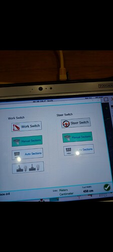
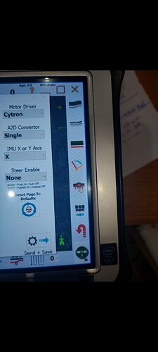
If you dont have pwm but , as you said dir is actually working.
So are you driving above min speed, or have manual steer in steer settings window activated.
There are no pwm if one of those two are not OK
At least one of them must be ok
Last night I put a V2.4 board I have on the bench and might have have replicated the issue? Sat the antenna outside the window with a test loom and a led on the lock pin. Fired up as per normal except tractor stationary due to fixed antennna. Went to steer menu and pressed the tractor to force steer and got no cytron direction leds and no signal on lock. Tractor would go green and make the right noise otherwise. Took off sensors and switches from the steer menu to no avail.
I got called to dinner, during which I though might be still be switch related, so went back and turned the steer wheel to manual under the vehicle configuration steer options menu, and took off the steer switch related section control in the work switch section of attachment. Back steer setting window, press the tractor and it works like it should with the lock pin lighting the led and the MA/MB lights working based on steer error as they should.
Proudly believing I’d solved it, I went back to see which of my changes made the difference, but it continued to work just fine no matter what combination I chose. Therefore it could have mysteriously sorted itself out during the half hour or so it was running unattended on the bench.
A such my advice for those viewing this thread who are testing on the bench is as follows:
-
You need to activate the steering manually via the steer settings.
-
This should activate PWM2 which enables the cyton and lock pin. If the MA/MB led lights shine and change based on the steering error left/right then you’re good to go
-
If that doesn’t work - go and have a cup of tea and see if it fixes itself.
-
If not, then ensure that in the expanded steer settings, Steer Enable is set to none, and Danfoss, Turn Sensor, Pressure Sensor and Current sensor are deselected. Disconnect switches and motors/valves. Set steering to manual and turn off steer switch related section control. Try again.
-
If it still isn’t working then you need to be probing the Dir 1 pin to observe toggling of direction based on steer error, and PWM2 which is enabling the cytron. These trace back to pins 3 &4 on the Teensy.
My unverified assumption as to what’s happening is the Windows program is proving “sticky” on whater enable steer command it’s sending the Teensy, i.e. the value associated with displayed buttons not necessarily getting sent through to the steer board and a toggle of a setting seems to sort it out. I’ve noticed that before on the imu direction. I sent the configuration as x-axis but it behaved like it was y-axis. It wasn’t until I toggled to y then back to x did it properly send it through to the teensy. In other words, even if a setting is correct, try changing it then changing it back to see if that fixes it.
Thankyou very much for taking the time to write such a detailed reply and for trying to replicate my same problem.
Do i still need to add that extra jumper wire under the cytron as you mentioned in your previous post above? My board is the earlier v2.4 that was in the 5.7.2 release not the later one found in the Google drive files.
It sounds like my software could be ‘sticky’ as you mentioned, everything else seems to work and all the led lights are the right colour.
I will definitely try this in the next few days and will report back.
Thanks again
Well, the board I tested had the wire, so I’d do it. I went and did all 5 boards at the time so I wouldn’t forget in the future (still have a couple left over waiting for friends to go from Panda to Autosteer)
I think it only happen at first start of AOG, so try from bottom (no power and no AOG) one more time and check again.
I believe I had a similar issue some months ago when I did office test of my panda system with 5.71 / 5.72
Nothing happens until I hit steer button at least one time, even when in manual.
Ok so ive had chance to do a bit more but still cant get no output on the ma mb unless i press the buttons.
Standard aio pcb v5 ecu 2.4
I downloaded the ino you suggested autosteer
_gps_teensy_v5_1_xbee.zip.
Flashed the teensy twice for good measure and no error codes. Was plugged into the pcb at the time.
I didn’t add the jumper wire as suggested as the trace is already there.
Been through setup wizzard.
All turn sensor current sensor pressure sensor is OFF
Steer switch set to 'NONE ’
Tractor settings steer switch control on red/manual
Machine control everything in manual. (Have also tried with ‘switch’ enabled and everything turned on)
Agio is showing everything green and connected
Pcb ethernet connected
Press PWM on steer setup, steer module light goes green on pcb, left turn red error cytron tests DIR 3.2v 0v on other pins
Right turn green error 0v on everything
Tested pins 3 and 4 on teensy as suggested (but cant find the proper pinout for this) pin 3 test 3.3v pin 4 1.84v
So im still at a dead end.
I have got the plug that goes into the end of the cytron if it can be used to rule anything out?
Any more help/ideas would be amazing
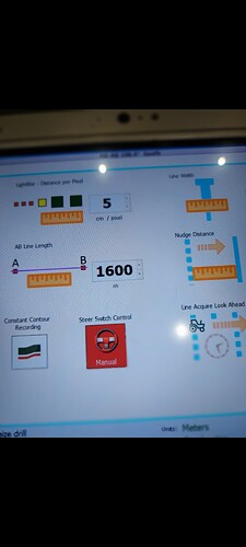
Do you have current sensor enabled? Is the threshold set at 0? I see you say it is off.
The reason I ask is this was keeping my motor from working previously.
It does not appear that is the case as you have a green steering wheel and green tractor compass.
Everything is turned off.
Everything is light up as it should be. Just cannot get any signal to the cytron.
sounds like you have been looking at the .ino files.
Can you check the following in the autosteer.ino file.
// *********** Motor drive connections **************888
//Connect ground only for cytron, Connect Ground and +5v for IBT2
//Dir1 for Cytron Dir, Both L and R enable for IBT2
#define DIR1_RL_ENABLE 4
//PWM1 for Cytron PWM, Left PWM for IBT2
#define PWM1_LPWM 2
//Not Connected for Cytron, Right PWM for IBT2
#define PWM2_RPWM 3
and make sure the pin numbers shown in the .ino match those actually connected between the cytron and teensy/nano. This should make sure the digital matches the physical.
I assume you have green Tractor to the left of your picture, like my prt scr here:
Dont mind the purple in mine at right it´s because i have no pcb connected.
There will ONLY be a PWM value higher than Zero if you have activated autosteer, so I repeat myself from post above CLICK one time at steer button! Just TRY!
This is my ino?
Using the 3 pins at the rear of the cytron. PWM2 through hole is empty
Picture of that
Here are 2 pictures. 1 showing pwm in the green error and showing red error.
Green tractor on. Autosteer on. Green light on pcb
No lights on the ma or mb when i go from left to right
pressing the MA / MB makes the motor move?
I had to put extra solder on the ampseal pins for good connection.
Yes. Pressing the ma mb buttons manual make the motor spin
Looking at the two pictures you are missing an important connection. They may not be labeled correctly on the silkscreen.
The GND pin on the connection is not connected. It is labeled as PWM2 on the silkscreen on the board but it is in fact GND. Test the connection here to see if it is GND.
You need to make sure of all of those connections. Something doesn’t look correct. Probe them to make sure they are going where they are supposed to be.
AHH — not a real error but just the difference between the two numbers red if it´s missing to move wheels to the left green if it´s missing to the right.
Now we have established that problem is somewhere on the PCB and it is not the missing PWM 2 because that one is not used with Cytron.
What you need is help from someone that have a similar PCB (I still run PCB V2) But I guess you miss some of the small connectors that is needed with your type of PCB
EDIT: I see you have a white and a Black wire for that purpose, but I don´t know how they are supposed to be connected.