I am going to get an 8120 set up with AOG, there is a 6 pin connector for the steering solenoids under the cab that I’m going to tie into. Obviously I need to tie into pins 3 and 4 to steer it from the cytron. Probably pass pin 5 through to the combine side of the plug so I can still use the armrest button to enable autosteer, unless that isn’t actually needed, hopefully someone has some advice on that. My main question is what do I do with pins 1 and 2 and how do they function? Is that how it knows to disable autosteer if I turn the wheel or is that for something else? I have a sensor on the steering column that I assumed was to disengage autosteer if I touched the wheel.
1 Like
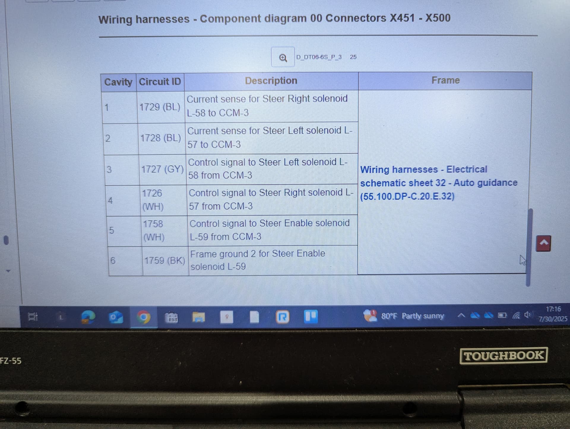
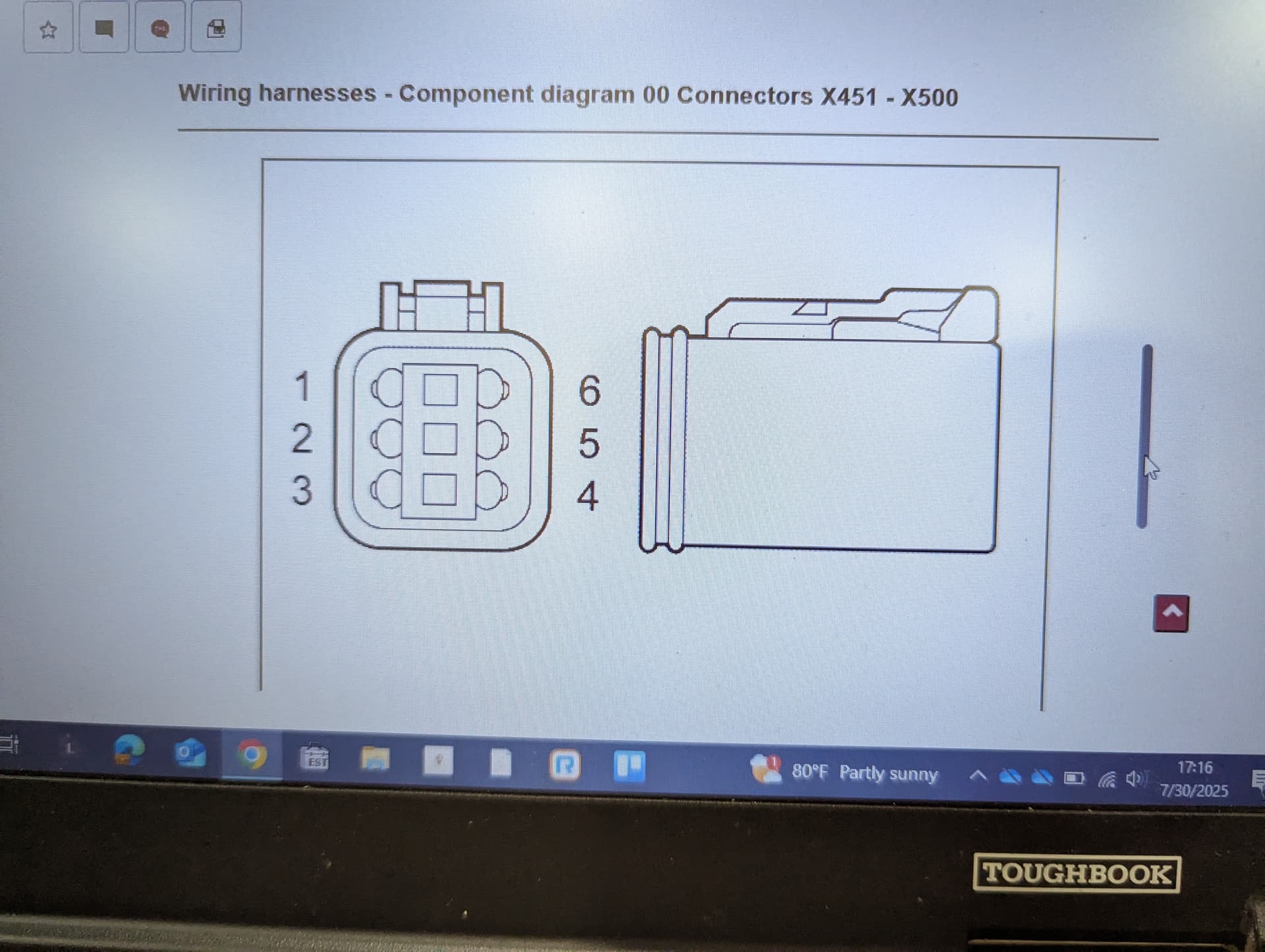
To use the factory autoguidance valve on a 8120 you would use pins 1&2 on ground, pin 3&4 to the power pins on the cytron, pin 5 will have to be wired to a lock relay that will be connected to your board, it is used for a safety lockout, pin 6 will go to ground as well, it should be pretty close to how a baraki valve would be wired up. You won’t be able to easily use the factory autoguidance button so another easy option would be to use a foot pedal to engage the autosteer system. As far as the steering wheel hall effect sensor it is at the base of the steering column under the rubber boot. If the machine was ordered autoguidance ready it may have the steering angle sensor installed in the left rear steering cylinder.
1 Like
Thanks! What are the purpose of pins 1&2 in the factory setup, do you know? It is autosteer ready so I was figuring on tying into the hydraulic cylinder and using that WAS, until it goes bad anyway lol.
I was going to use a footpedal for the autosteer engage, I mispoke. I was referring to the button that “released” the safety lock for the autosteer. I was going to keep pin 5 running into the factory harness so I could keep using that button but I’m not stuck on that plan. I assume I’d wire that up to pin 7 then for the AIO 4.5 Standard board?

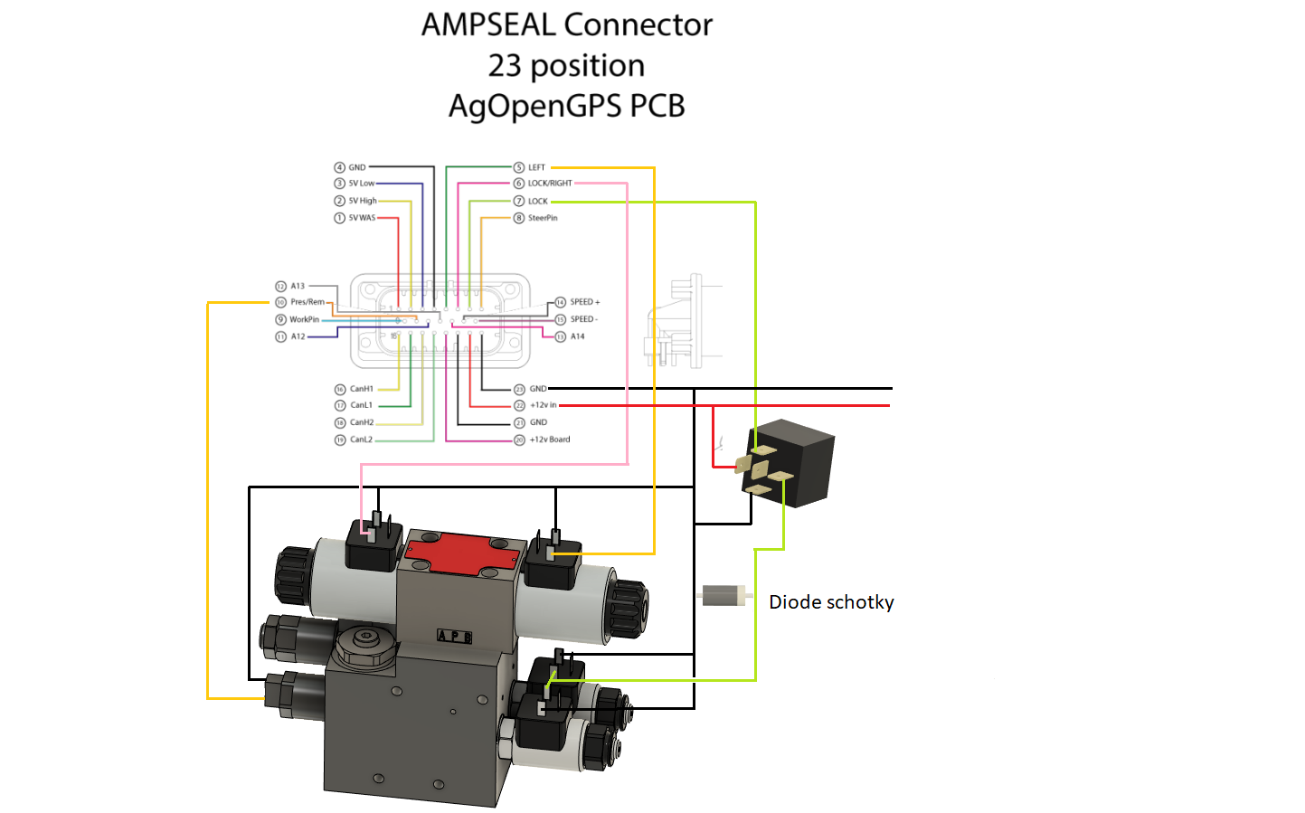
I’m not sure if you will be able to use the factory auto guide switch as I believe the power for that solenoid comes from the nav controller. I think the current sense wires are just for monitoring of the coil, if the coil is bad it would be able to sense on the factory system that there is an issue and lock out the steering. As far as wiring I would follow the picture I attached.
1 Like

What would be the proper way to wire the factory hall effect steering sensor(if any)? It’s 2 pin plug, the factory harness has 7.7ish volts on one pin and ground on the other.
Are you holding the plug connected to the sensor also seen in picture?
Yes I was. I’m guessing it’s only supposed to have 5v so it should be easy enough to power from the board. I tried hooking 5v to the power pin and the other up to the Remote/Pressure(10) pin with no result.
Would putting a resistor between pin 10 and ground be the proper way to get it functioning or is it even possible to make this sort of sensor work with AoG?
Stop here!
That sensor is definitely not a was, but probably some kind of reed sensor counting the teeths of the toothed wheel, cutting connection each time a tooth is passing.
Is that toothed wheel attached to the steering wheel somehow?
A hall sensor normally have three wires power, GND and signal out
It seems case 8120 is a combiner.
You say it is steer ready!
So there must be someone that have used the main connector for original steer computer (as have been done for CNH tractors.
EDIT
Follow CTDMN instructions above, and find the was cable from steering cylinder at back wheels
I suppose the sensor you mentioned to disengage autosteer is the one by the toothed wheel (will work with AOG.)
You should check what ccm 3 is
Yes it is a combine. And yes it is steer ready. Sorry I wasn’t clear on that. From what I’ve read this machine doesn’t have everything on the canbus system that I would need and at minimum the WAS values aren’t on their own pins on the Main Connectors for the factory autosteer. It doesn’t appear that the steering wheel sensor is either. Since there is no factory autosteer enable button on this combine to access with canbus, I figured it was much easier to just run my own wires.
As to whether it is a hall effect or reed sensor I don’t know for sure, @CTDMN mentioned it was a hall effect so I went with that. I got the sensor functioning with a resistor to ground as I mentioned, it cuts power when the teeth go by the sensor. The sensor requires 5v and ground and in the schematics I looked at, it appears that is how it works from factory as well. The ground coming to this sensor is tied to a potentiometer.
Now as I said I have the sensor functioning as it did from the factory I believe, but I am not sure how exactly I need to configure AoG. I’m guessing it needs to be a count sensor, I put a jumper on the remote/pressure pins on the remote side as instructed in the wiki for count sensors. This however did not work, that cut my power to the sensor. When I pulled the jumper off the power returned. What does AoG consider a count? is it just closing contacts as on a reed switch or can the jumps from 0-5v be considered a count as well?
I have followed @CTDMN instructions(thank you by the way!) and I have steering and WAS all working, the only thing remaining is just the steering wheel sensor.
Set counts in aog,(turn sensor in steer settings) jumper on pcb at remote. Connect pin 10 (press remote) on pcb to one pin of your steer sensor the other pin to GND)
You can check first by setting like 5 counts , then connect pin 10 to GND rapidly at least 5 or 6 times, and autosteer should disengage
It does not work. This sensor requires power. I’m guessing that means it’s not compatible with directly connecting to AoG. Which isn’t a big deal. So if I’m understanding correctly, what I want is something that just opens and closes the circuit to ground? No voltage needs to be involved for a count sensor?
You should measure the voltage on pin 10 when you have connected the pins to remote on the pcb
Ok, so does the voltage need to go from 5v to 0v to register as a count then?
Had to check myself, mine say 3.6 V I would have thought 3.3 V, as it is connected to a teensy pin.
But yes one count each time that pin I “dragged” low
, aka connected to GND.
I am sure your sensor just connects each time a tooth passes, no matter what voltage you have.
Ok, I’ll give it another shot then.
Yes it does, but I think it needs 5 volts to power up. Is that going to be safe to put to pin 10 if that’s going directly to the teensy?
Edit: I can actually power the sensor from 3.3v and it appears to function. Now just need to see if there’s a 3.3 source I can rob power from on the board.
The only source you can use is the number 10 in ampseal. As I just stated above is has something like 3.6 V when correct pins on pcb are connected.
EDIT: to point out how it works. The pcb provides the voltage to pin 10, there is a resistor in the line so you just have to connect to GND to make the voltage zero, and that is one count!
1 Like