Honestly didn’t go through the wizard but directly from the settings… Changed settings and saved the configuration into the teensy…
Probably I miss something. I will check again and let you know!
It looks that way to me.
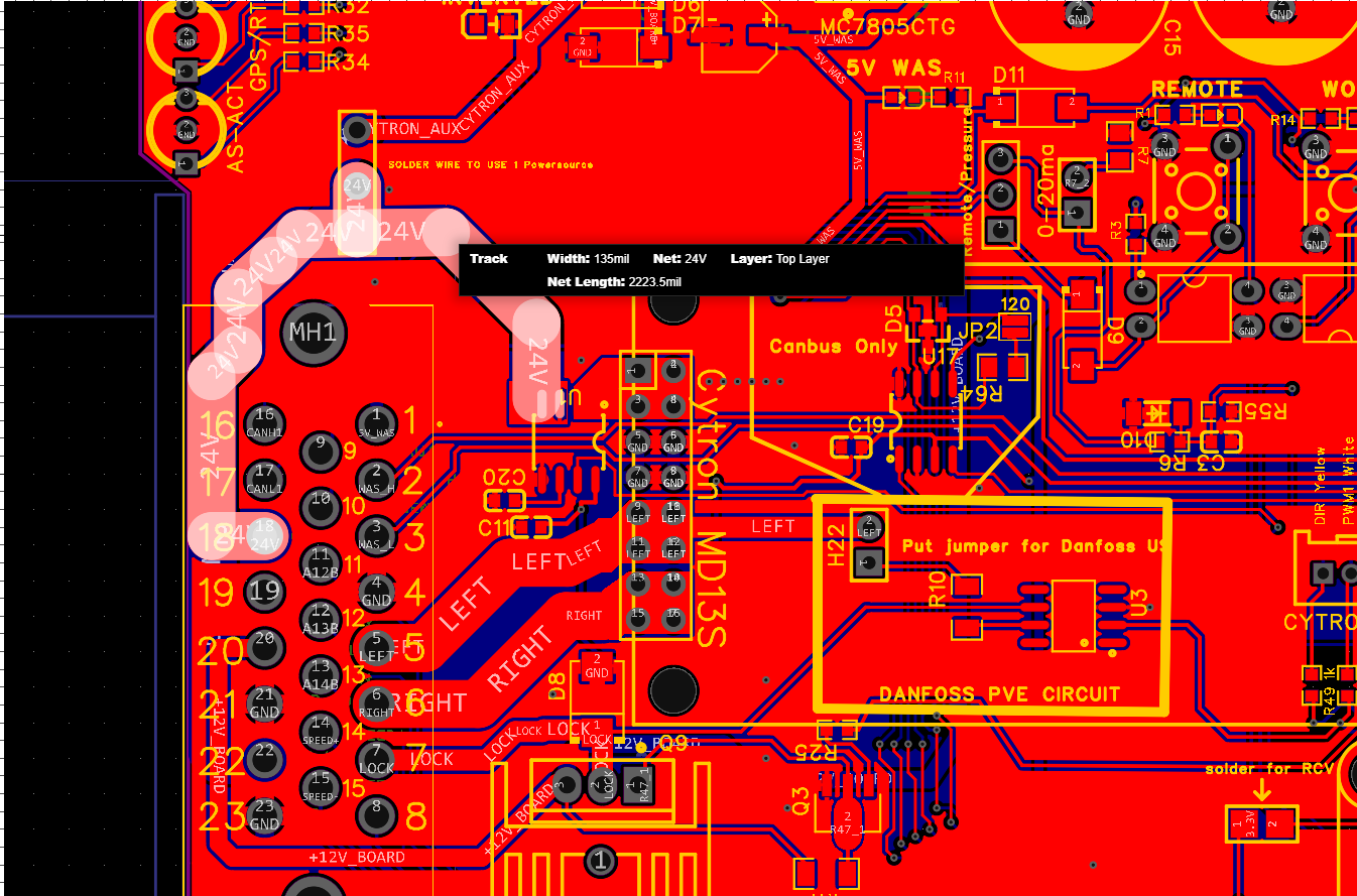
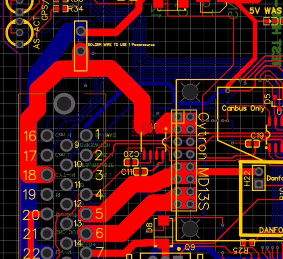
Pin 22 should be +12v_in not CYTRON_AUX and only connected to the top via.
Thanks for the suggestion of going throug wizzard!! It finally work!
Am glad it worked
Happy autosteering ![]()
2 Likes
You’re right, good catch
Pin 22 and 18 are already interconnected on the bottom side on the vias intended to interconnect them.
I think it’s a design error.
Must be cut at the bottom to use 24v motor.
Issues fixes here:
will this be updated in the Gerber file? I have not ordered my board yet and would prefer not to have to modify my board by cutting the trace, I can wait if it can be updated.
1 Like
The ADS1115 address is not set.
The ADS115 breakout board has the address pin connected to ground through a 10k resistor.
I would suggest doing the same so it will behave the same as the breakout board.
In my attempt to learn something new I ventured into the easyEDA world and made my attempt to modify the board so that the pin 18 and 22 were not connected only by a wire if wanting to use 12 v. pictures shows that I renamed the “net” name for the 24V trace to “24V” and moved some traces. The pictures show that the pin 18 and pin 22 traces are separate now. Does this look correct to the professionals on this forum as I am very much a novice at this? If this looks correct what steps do I take to put this into a Gerber file and possibly share with others on this forum. Just trying to contribute a little to this great project.
1 Like
Are they all on top of each other on the same layer “top layer”?
By removing the dotted lines around the board, you can see the strokes better.
The board should be updated, v4,2
Check on the GitHub board repos.
1 Like
Thank you for updating the gerber file. Any chance the EasyEda file can be uploaded? Not meaning to sound needy, just like to like to keep files and understand the boards. If there is a way to use the gerber file let me know I cannot seem to import gerber files into EasyEda.
Very nice pcb!
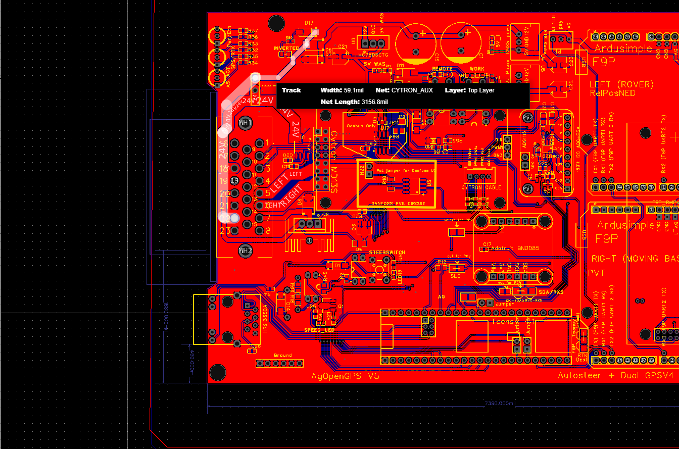
to understand: is a voltage converter of 12 to 24 V already installed for Cytron?
No you will need to add this extra. Not all users use 24v motors alot use 12v with good success.
for the files to order, go to the Github board repos:
1 Like
Ok.
So i have to wire the converter to pin 18 and gnd?
That is no problem for current sensor on the pcb?
Yes, 24v+ to pin 18, GND you don’t need, it will have a common ground taken from pin 23.
You will solder a jumper wire on the PCB to connect pin 18 to Cytron input via current sensor.
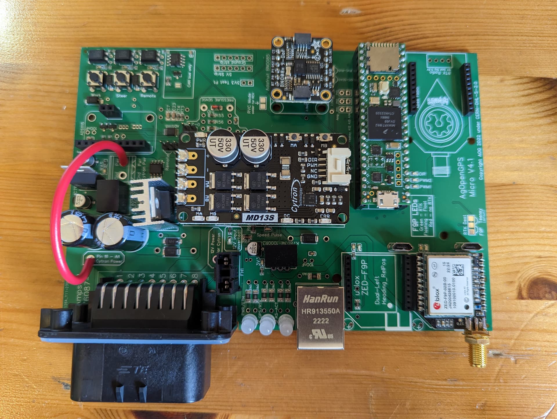
https://discourse.agopengps.com/uploads/default/original/2X/4/4d354e3f7af186fabc697552514a03c33978919e.jpeg
A picture here of the jumper wire as teddy described
thank you very much!
i’ve seen the picture above. now I’m sure how to wire that.
so this is only an issue on he standard board and not the micro?