could someone answer this?
how much power may draw from pin 7 on amp seal connector from board. ? going to use it for powering the hyd valve when auto steer engages. using the Baraki Valve , @baraki . how many amps does the valve use? do i need a relay ?
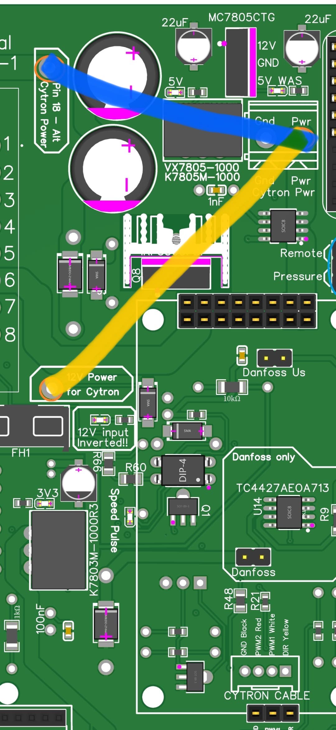
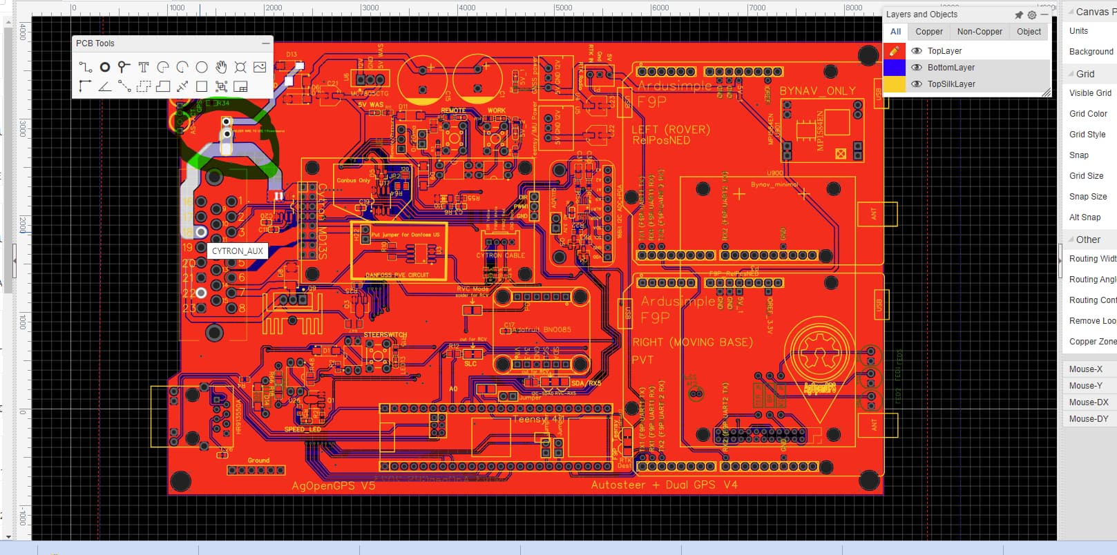
Help me understand the new 4.1 STD boards power. I will be using 24V to power my motor. Main 12V power comes in on pin 22 and and I will bring in 24V on pin 18, with this setup I would NOT connect on board were it states “Solder wire to use 1 power source”. Reason for asking is when viewing EasyEDA and I hover over pin 18 or 22 they look like they are connected already as they both light up the same traces. Picture attached shows traces lit up when hovering over pin 18 and pin 22 lights up and it looks the same when I hover over pin 22. I am new to EasyEDA so bare with me.
I was comparing my board to a picture and noticed i am missing something in the “Mc7805ctg” spot. Am i supposed to have something there and if so what is it?
Hello Farmers!
I just finished to assemble the last PCB 4.1 all in one.
I have the position and rtk fix. I have the wheel angle sensor information that come into the program and I can see it but I can’t activate the motor through the program.
The dir led is orange but no pwm signal. I’ve the cytron installed on the board and if I press the MA and MB button the motor turn.
If I press the pwm button in the steer configuration nothing happen.
Any idea how to check if teensy send the signal?
Have you been through the steer setup wizzard? There are options to tell it how your steering it and how your activating autosteer. Make sure these are enabled correctly and you get an option to save and send your settings.
Also had a similar problem on my standard aio where the pwm buttons didn’t work. Finally narrowed it down to two soldier joints touching on a teensy 4.1 i bought with the pins already soldierd