On the right side towards the top there is a box with several options. This is where it stores this files on the F9P. By default I think only the top two are selected I always select all of them as some do not save the config on a reboot but not sure right now which.
1 Like
Hey Guys,
im doing my own V4 all in one PCB + system build.One question i do have, and i’m probably overthinking it, but how to i set up my 24V system with the V4 micro board?
I soldered a wire from pin 18 to the Cytron PWR, pin 18 will be connected to the 24V out of the converver. converter should to straight to ground and 12V outside of the AgO system right?
but then how to connect the motor? Motor only has 2 wired, red an black. Pin 5 is the motor left so thats one motor wire(red), is pin 6 (motor right) the other wire (black)? or does that need to be ground? Pin 5 and 6 will then give 24V through the board from the Cytron, and where do i put the ground of the 24V side of the converter to close the circuit? the minus side of the cytron will need to be connected to this 24V ground too, do i need the Cytron GRD hole on the PCB to connect that? like i said probably overthing but could use your help. ![]()
Overthinking it.
24V+to Pin 18
Pin 5 to motor left
Pin 6 to motor right
Ground will be obtained from Pin 23 (make sure wire is large enough to carry current of PCB and motor), so ignore the ground from the 24V converter.
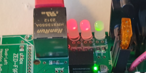
Solved! Got GPS ![]()
Finally 3 leds
It was annoying simple, perhaps I just have missed this information:
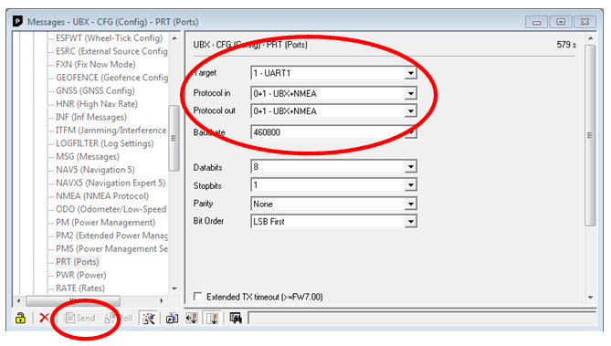
In u-center
View->Message view go to UBX->CFG->PRT
Added info for UART1. I am not sure about the protocol might need to change it later…
Pushed send
Save config to be sure
1 Like
Yes, very simple.
So all is working now?
That means, your f9p configuration was’nt stored.
I am receiving a position in AOG. Now I am currently setting up my NTRIP caster. I’ll guess it will be some fiddling with settings to make it work. But at least I am moving forward again.
Setting up the caster I read that in ucenter send needs to be pushed twice. Could perhaps be part of the issue. It might be more settings I need to change…?!
You’ll need ubx nmea & rtcm3 if you’re using ntrip
1 Like
Thanks for the input. Rtcm3 was configured in a tutorial I followed for the base so it make sense to be included in AOG.
If I understand correctly all F9P settings should be included in the configuration file. If that’s the case my easiest way is just to get it uploaded and saved correctly.
I wonder if anyone can point me in the right direction. I am getting my board together and introducing the WAS however there seem to be 4 wires to it from PCB however my WAS (the one Brian recommends ) has three. Is there a pin out diagram of a was to show which to use ? Thanks

WAS Pinout:
- Pin 5 +5 VDC
- Pin 1 GND
- Pin 4 SIGNAL

Now on the AIO v2.4 AMPSEAL:
- Pin 1 +5 VDC
- Pin 2 SIGNAL
- Pin 3 Is also signal but you don’t use this
- Pin 4 GND

I don’t know if other boards are different
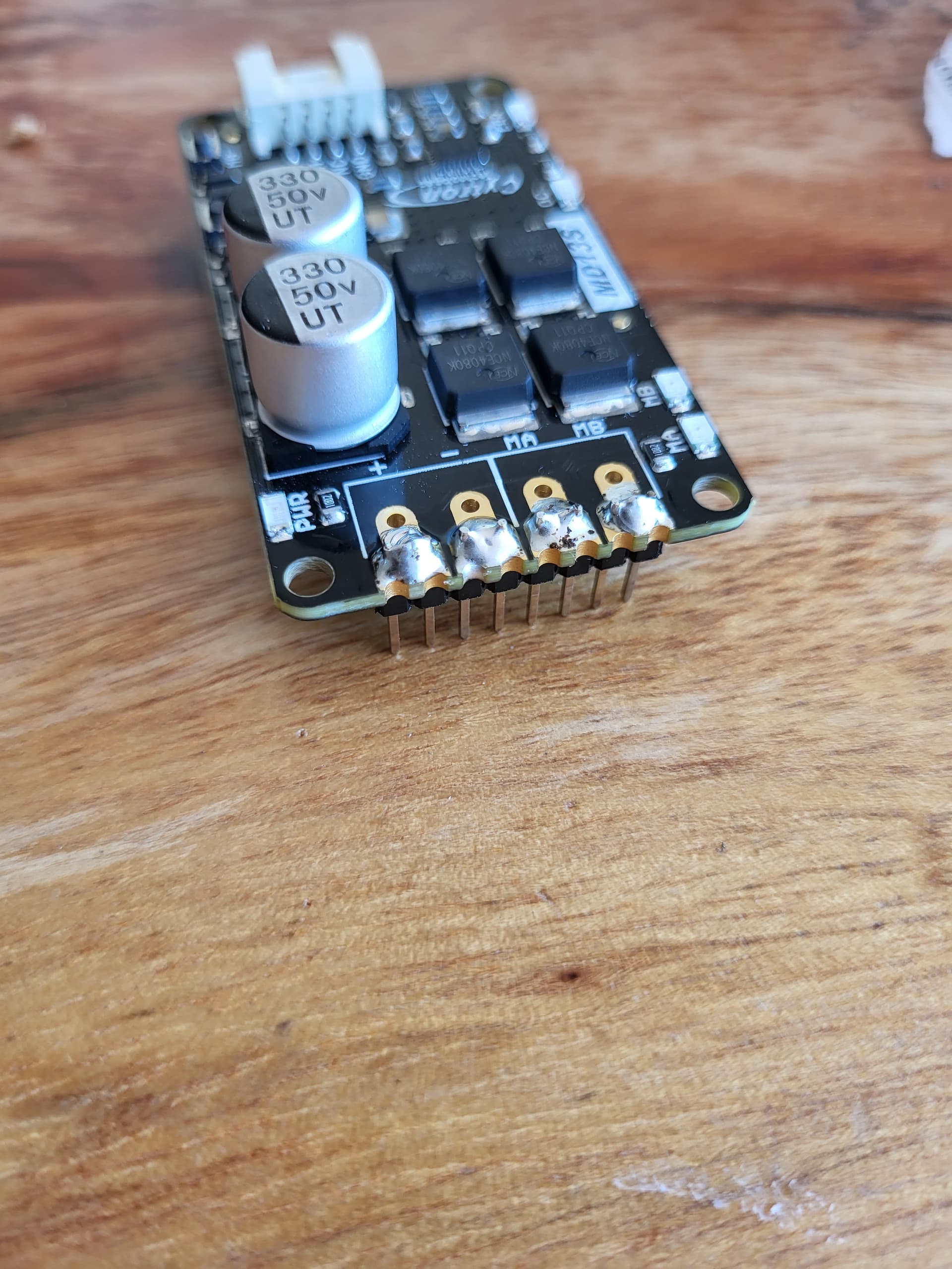
Hello, I am currently integrating the cytron and wondering about how many pins to solder on the DC input/ motor side. Most people seem to only use the closed-hole pins (2 per channel). The current rating of the double-row female header on the AIO pcb seems to be 1A per pin, so I am wondering if also using the open-hole pins is better…
Or was the double row female header only used to make the AIO compatible to other driver models aswell?
Good morning. Any updates on AIO Standard pcboards?
I have been soldering on the second header, it is there to allow higher current draws. But I am not aware of any failures with a single header. To solder the second header you can place it in the AIO board to hold it in place and then solder it.
2 Likes
From the sounds of it the design is finalized and they are just waiting for it to be released any day now.
Hi guys,
What amperage did you use for the fuse for 12V or 24V motor ?
Do you have a supplier link ?
Thanks
Every motor has its specs… read what’s its stall current that’s maximum it can draw… probabbly about ~10A…
Ive got a 3amp fuse on my board… think the phidgets 24v motor draws 3.2amps at maximum headland turning. @TeddyStamford posted a video of his results i think