Yes DPDT relays could be used. The rate app does allow for multiple relays to be used for each section.
In this example relay 1 for section 1 will be on when the switch is on. Relay 2 for section 1 will be on when the switch is off.
Yes DPDT relays could be used. The rate app does allow for multiple relays to be used for each section.
In this example relay 1 for section 1 will be on when the switch is on. Relay 2 for section 1 will be on when the switch is off.
I mean a PCB with DPDT, likes Gorms PCB
Schematic_Section_and_Rate_Control_Unit.pdf (741,4 KB)
This PCB allows you select mode on each section (Manual/Off/Auto), very usefull
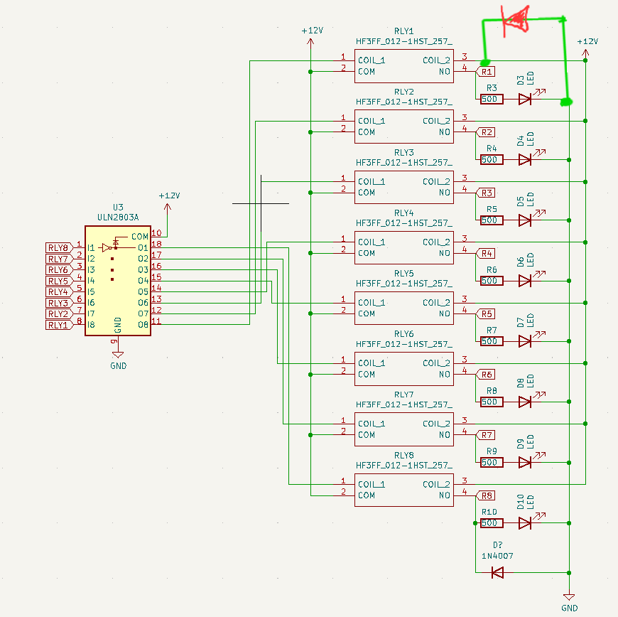
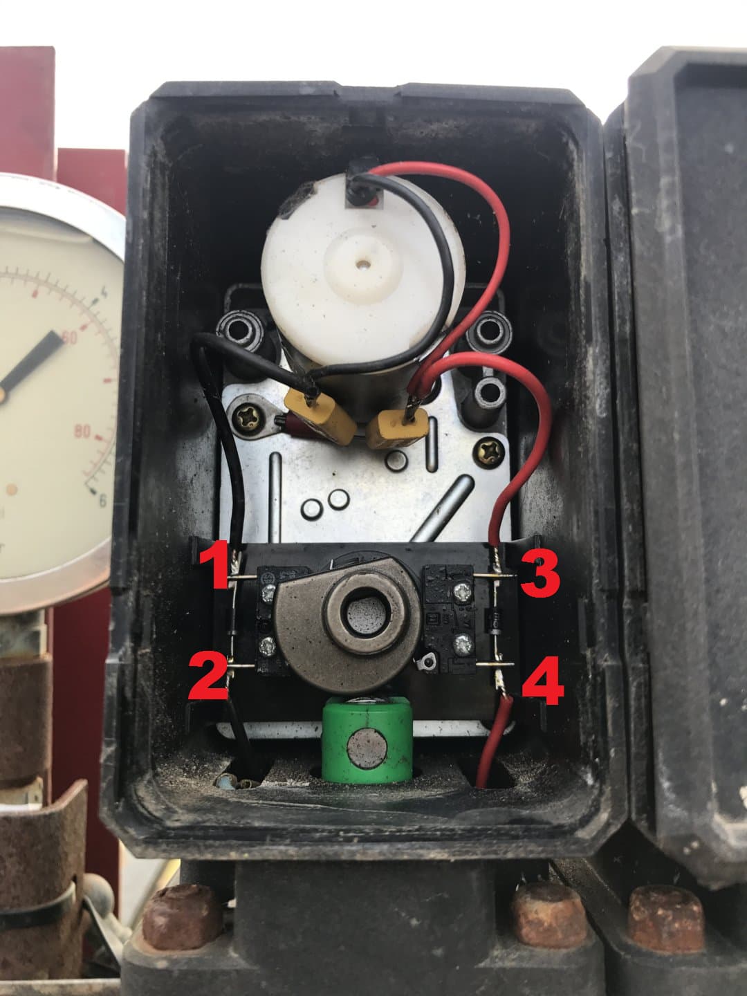
Probably ammounts to the same thing, but I put the diode directly on the 12v out to the solenoid, connection 3 of the relay. Tried to draw on relay 1 what my circuit looks like…if i have read the schematic correctly.
DPDT relays could be added. This would double the number of pins required.
A separate switch pcb https://github.com/SK21/AOG_RC/tree/master/Modules/SwitchBox is used for manual/auto, off/on, master off/on and pressure up/down.
Yeah, i know but Manual/AUTO turns all switches MANUAL or AUTO, for example in Gorms PCB you can have only one switch on MANUAL and others in AUTO, on each switch you can select the mode, i think it’s a usefull feature.
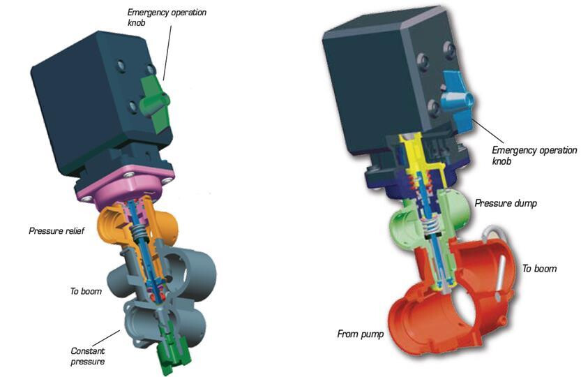
Most sprayers today use valve motors with limit switch, and they need a reverse polarity
Have you used this feature (manual/auto/off)? How does that work? Do you have individual section flow control and flow sensors? Is this common on sprayers in Europe?
A niche pcb could be created for valve motors. Some like this one TeeJet 1" 344 Series Electric Shutoff Valve | 344BEC-24-C | TeeJet | Barndoor Ag only require an on/off signal. The valve itself provides power in both directions. Probably easiest to use Gorms pcb.
I am using the Gorms PCB, the only drawback it has is that it does not have flow control, and all three modes work on each switch.
Hardi, Teejet, Arag, Amazone… all use motor valves (3 ways)
Hello Guys,
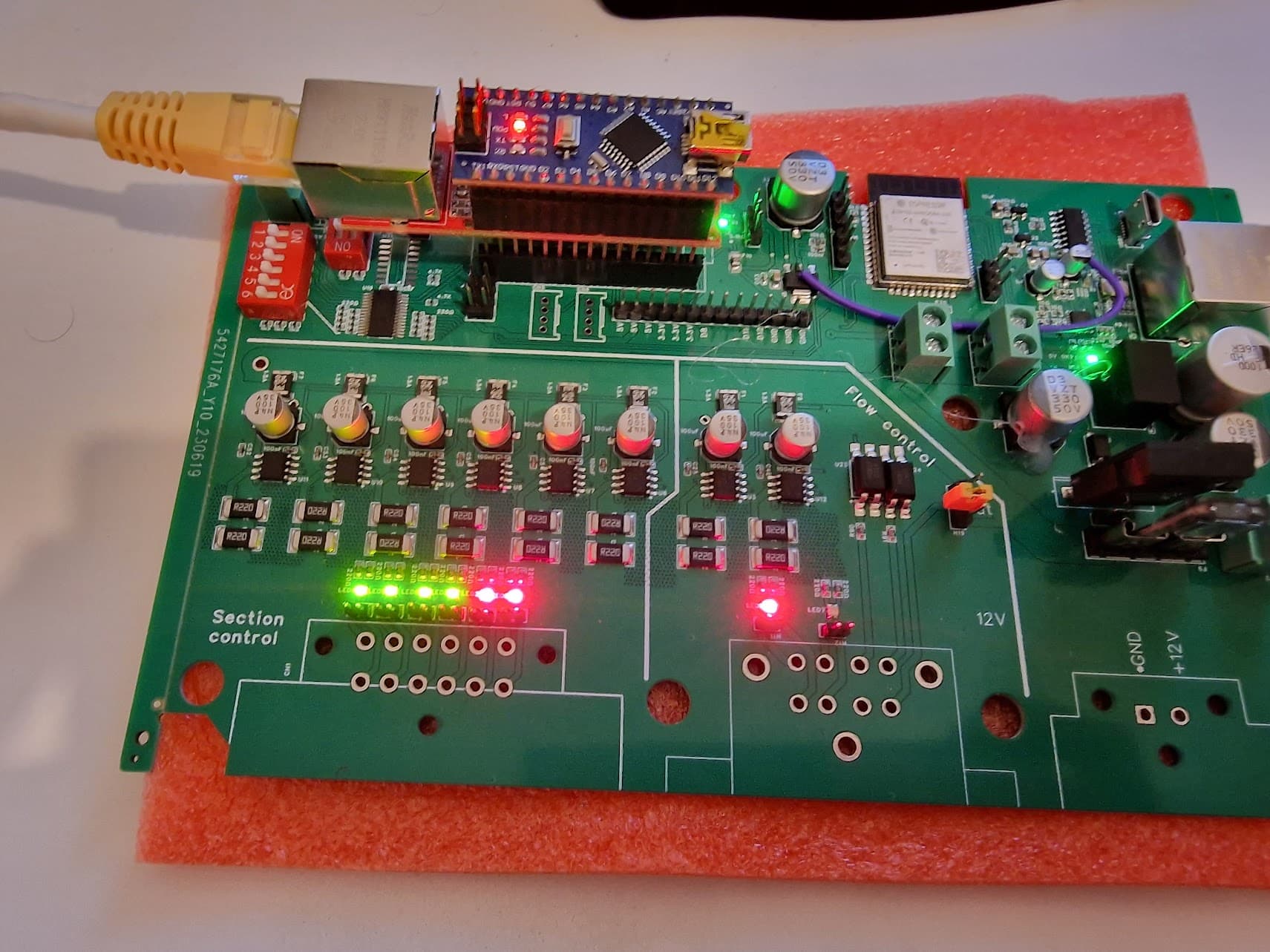
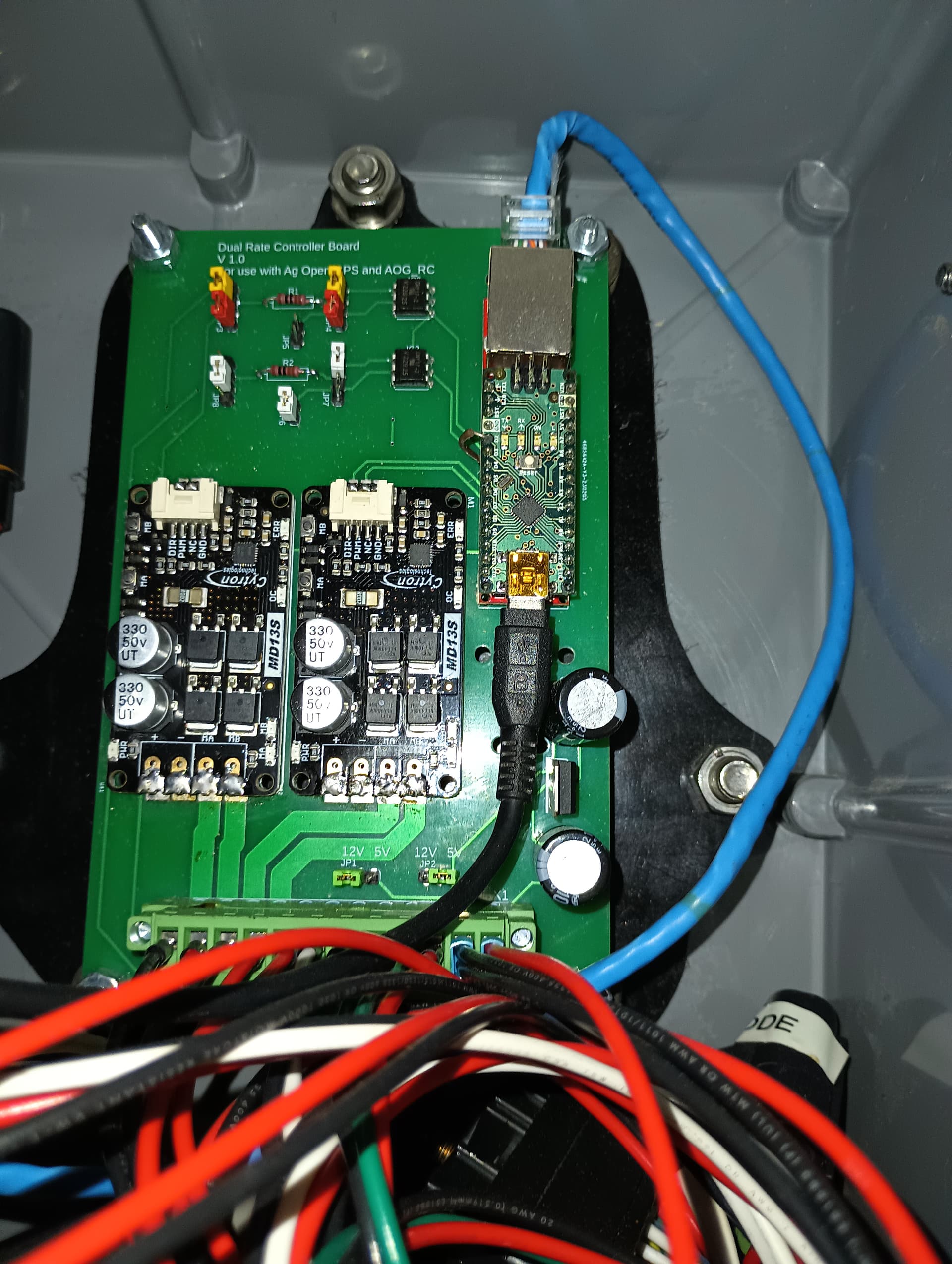
We started to design our own PCB for AOG_RC (instead of building one that’s readily available ![]() )
)
The idea was to:
What we’re still struggling with is the PID part.
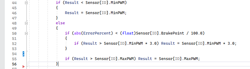
Our PWM value is often way out of the expected range of -250 to 250.
Our Valve needs 150PWM to start but we often get invalid values 3*minPWM, etc.
If we move minPWM down to 50 then at least we stay within the limits.
MaxPWM can also go beyond the set limits. There’s no enforcement for it. (We kinda expected it to stay between 0 and 255 )
The PID function even looking at the code is a huge mistery for us. What are the values we’re expected to configure in the UI?
Having 5 parameter for the PID is really complicated.
AOG has only minPWM then when we’re within the brakepoint range it starts to use minPWM + (P * error) instead of maxPWM. In my opinion that’s super easy to follow.
Is there any default values we should be looking at for the PID control to work?
What are we doing wrong for getting out of range PWM values?
Your pcb looks good. How is the range with the ESP32? I tried to do similar with a ESP 12F but the range was very disappointing.
The PWM should have been limited to the max setting. The values I tested it at never encountered the error. Here is some revised code that should help:
The Integral and Derivative parameters can be set to 0. Proportional on my sprayer is set to 40. There is a large range to give finer adjustment.
In the brakepoint range with AOG, pwm is calcuated with p * error. It is limited by ((highPWM-lowPWM)/Low_High_Degrees) * error + lowPWM. The rate module needs some way to limit pwm in the brakepoint range. It uses 3*MinPWM. Maybe the AOG method could be adapted to the rate module. It would require some testing to see what the equivalent of Low_High_Degrees should be.
Our problem is that we need 180-200PWM to get the valve moving at all. And even then it takes seconds to go between its limits. (PCA could do 4096 levels of pwm but we simply *16 the value)
We must set minpwm to 50 as if we do anything over 90 we likely end up doing 270+… That’s totally out of range.
Currently we use the PCA even for this motor but I think using a DRV would be a smarter choice as it could handle even more amps. It could be driven directly from the ESP32.
That way we could easily have a daughter board that could handle 8 motors/solenoids with no relays.
We did try 40 integral but maybe our flowmeter ticks on the bench are too small?
We’ll play with the AOG style PID as well and let you know.
I don’t think you can get to 270 with the revised code. It should limit the pwm to the maxpwm value.
I don’t use any integral. Just P.
So I am trying to get rate control set up on our 5 section sprayer. Can RC tell which sections are on on AOG? Or does it assume all on or all off? I don’t actually have anything installed yet, just trying to figure out how everything works
btw we’re not using WiFi with ESP but ethernet.
WiFi / bluetooth might be good for debugging / monitoring purposes though.
There’s also a CAN transceiver (untested currently) might be good for ISOBUS with the opensource library ![]()
I’ve modified the code to have the Result start with -/+ minPWM instead of 0 then we could get much smoother results between minPWM / maxPWM . Needs some field testing ![]() (+ we’re still not 100% sure about ethernet wiring…)
(+ we’re still not 100% sure about ethernet wiring…)
Rate control controls the sections and aog is along for the ride which paints only when the certain section is controlled on by the RC. All the time settings in aog are used to turn rate control on and off from your Headlands.
Is the rate control code and sample PCB still in the download of each version? Says so on the GitHub but can’t see it having downloaded.
Looking to have the code tweaked to run stand alone to AOG
I don’t think so.
If you click on the Source code (zip) file in the release all the info is there.
In the app there is the option to simulate speed on the switch menu. This should allow use without AOG. It is all untested. But the whole switch form needs to be redone. It and the product calibration screens are not as clear as they could be.
Has anyone sucessfully used this to control a Air Drill?
Also looking at the Nano RC12 PCB it looks like it only controls 1 Rate? So if I had 4 Product meters/ flow meters I would need 4 PCB’s?
Also Excellent work on this, will Variable rate be introduced back into AOG?
Currently looking at Controlling a Morris Series 8 Tank that has been converted to Trimble Field IQ, I do not have the monitor and they are $20,000, I do not need variable rate.
I built a custom pcb that uses the current nano code. It can control two rates at once. I am using it on our fertilizer truck. The software is set up so that each nano can control up to two rates.
Do you have the Gerber Files for that PCB?