Which version were you using before? Did you update the pin definitions?
Sadly i deleted all the files so there is no conflict with old folders. I don’t know what version was in use, but i downloaded it in late November, 2023. Pin definitions in the new Modules window, where is listed flow1, flow2, dir1, etc? I thought i did, but maybe should try one more time tomorrow.
Cause now, clearly signal in D9 for PWM is pulled up from 0.1 to 4.8 volts even with data cable removed.
1 Like
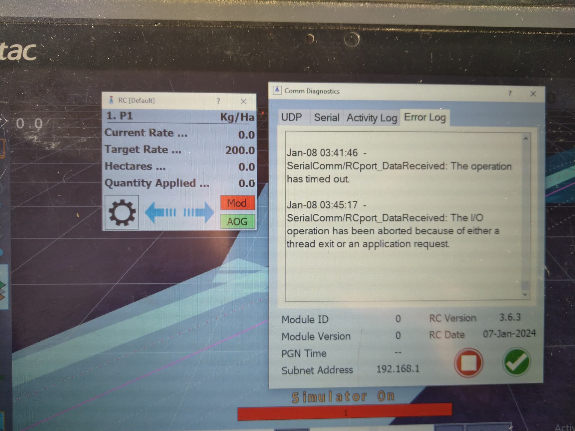
Changing PIN numbers can’t cange anythig, cause Module is not connecting. Made a fresh download and Nano one more time got Nano folder file uploaded succesfully, but strange, that error log still shows ethernet related error.
USB connection. There should be a stream of data in the serial window.
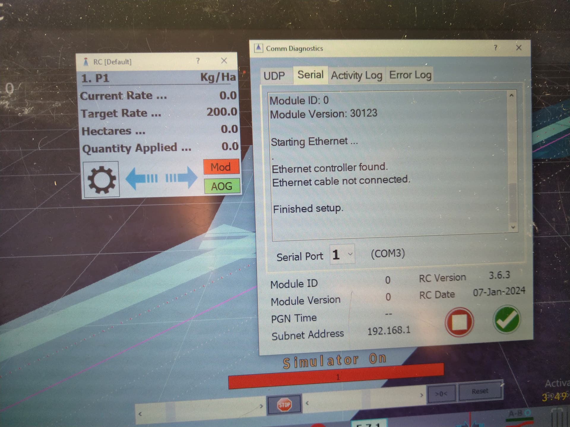
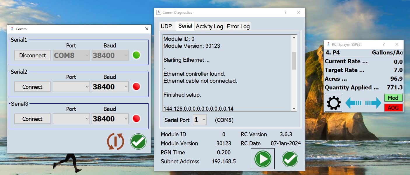
On your screen it shows the ethernet controller is found. Is it the ENC28J60?
No, Ethernet and other modules are still on the shelf and working only with serial connections via USB. Just found out, that maybe OEM Nano D9 output is corrupted and switching on itself- first time ever. Thougt that is generic, cheap Nano problem. But still, something is odd.
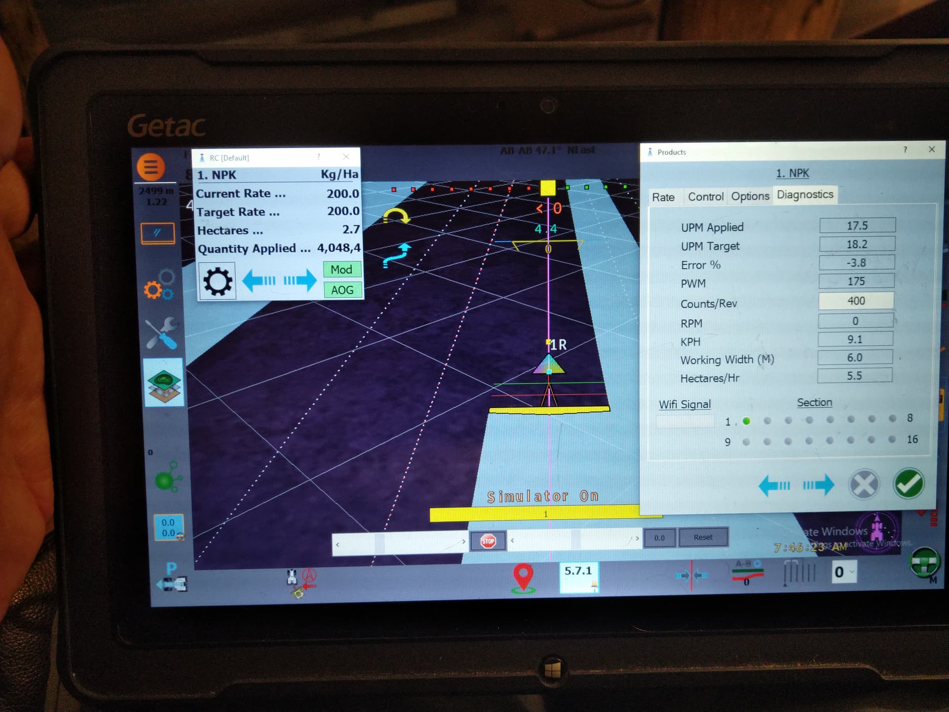
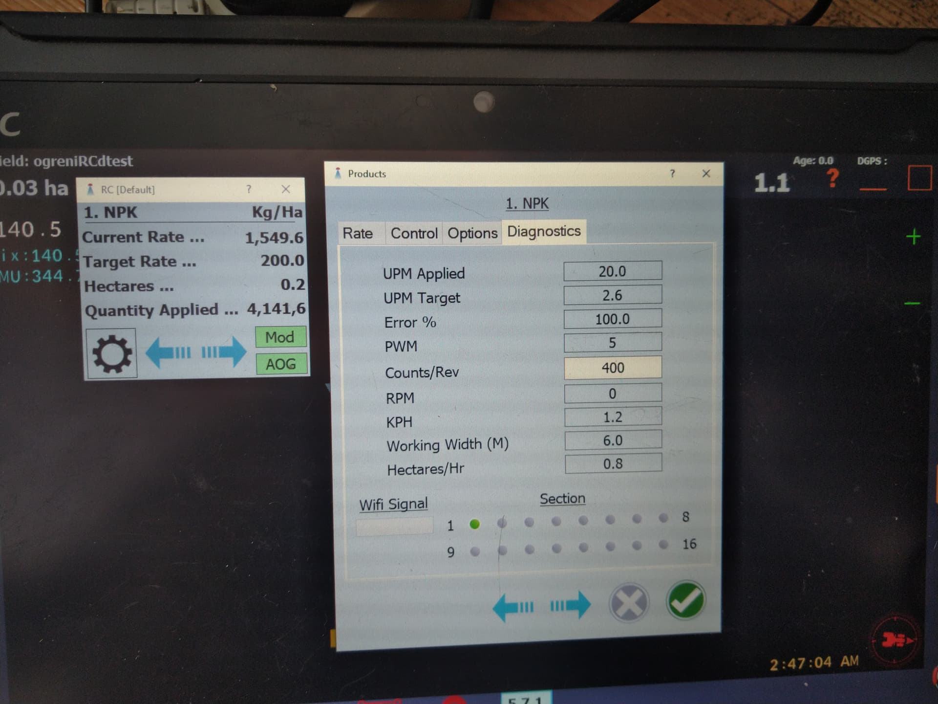
Motor mode is running, but after 6km/h, rpm max stops at 44rpm and PWM is rising to max 255 to try to speed up without success. With >50ms mode and <50ms pulse modes. Module - Config1 and Pins windows is all zeros.
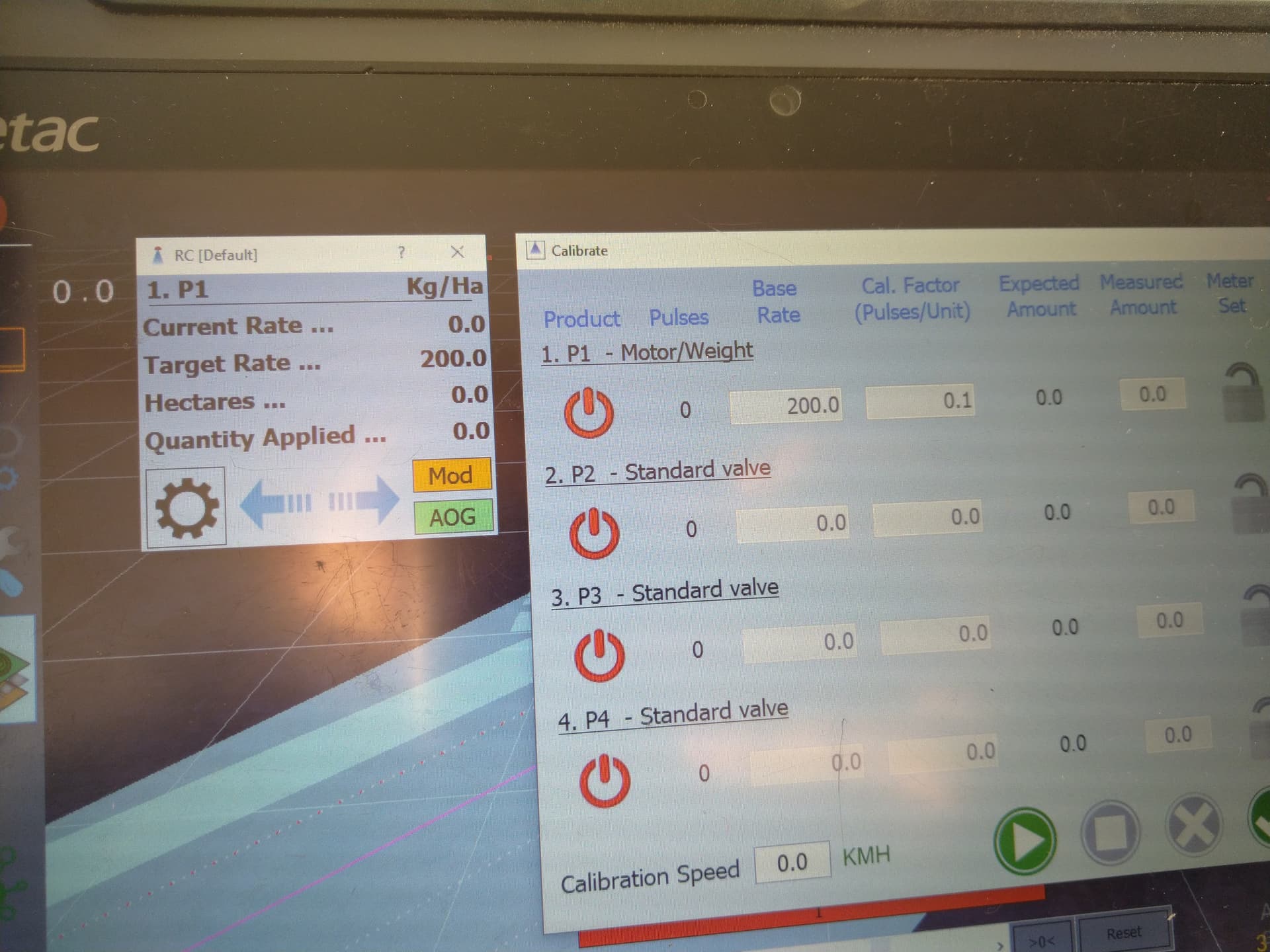
But Motor/Weigt is showing nice and linear PWM gain in Diagnostics window and Current rate folows nice, but actual motor is still. Could it be, thats it is affected by simulator?
In calibration window rpm’s are mesured correctly even at max speed +/- 400 impulses pec revoluton.

And is there any difference, what INO file is used - from RC folder, NB or OB?
Sorry for so many stupid questions
NB/OB depends on whether the nano uses old bootloader or not.
Did you get it connected?
On the module config page you can load the defaults with the bottom left button. What pcb is it? If you use the ? on the bottom left button a page will be displayed with the values for various pcbs. Any changes made on the config pages can be sent to the module/nano with the upload button (bottom, second from the left).
I got my second Nano fried. First one can connect to RC, but still has pin 9 defect and second one can be uploaded with new soft, but can’t be connected with RC com.
Now I’m taking couple days off, to think thought possible faults.
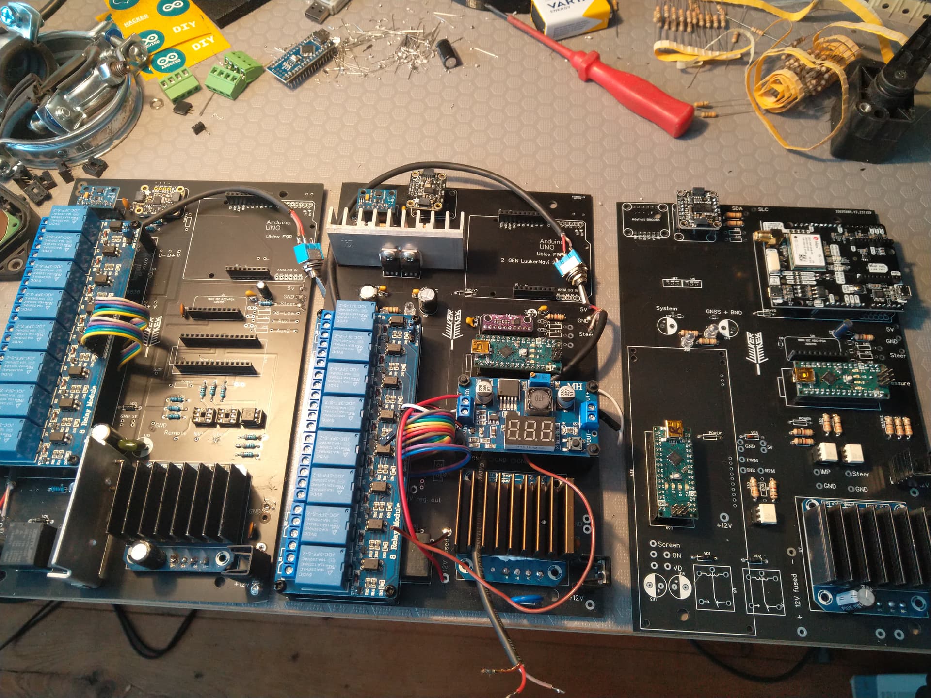
PCBs are my custom design. The one on the right is the 3. Gen what i am using with Rate Control. For the main drive motor i don’t have problems, but to prevent from big spikes in voltage, while turning steering wheel with engaged motor, there is 18v varistor, 5.1V Zener and 15V zener diodes and Shotkey diode with 16A rating as reverse and over current protection.
Soon should add varistor to RC motor and some kind of filter to encoder. Wires are short and very close. Maybe while testing, sudden peaks generate some spikes and fries controllers.
Also will change pinouts as in latest PCB example picture: D2 for Flow and D4, D5 for DIR and PWM
Previously in PDF was D3, 6 and 9 and it even worked with latest soft for one minute.
1 Like
Read one more time SK21 message and played arround with a blue arrow button on the Module window. Non of arduinos are fried after all
Also disabled simulator, added A-steer and GNSS modules, but still in Motor-weight mode rate is going up with the smallest change in speed, despite actual rpm is 0 and RC controll app also shows 0.
Could it be, that wrong signal is somehow transmited trough serial port via cable or AGO dirrectly affecting RC?
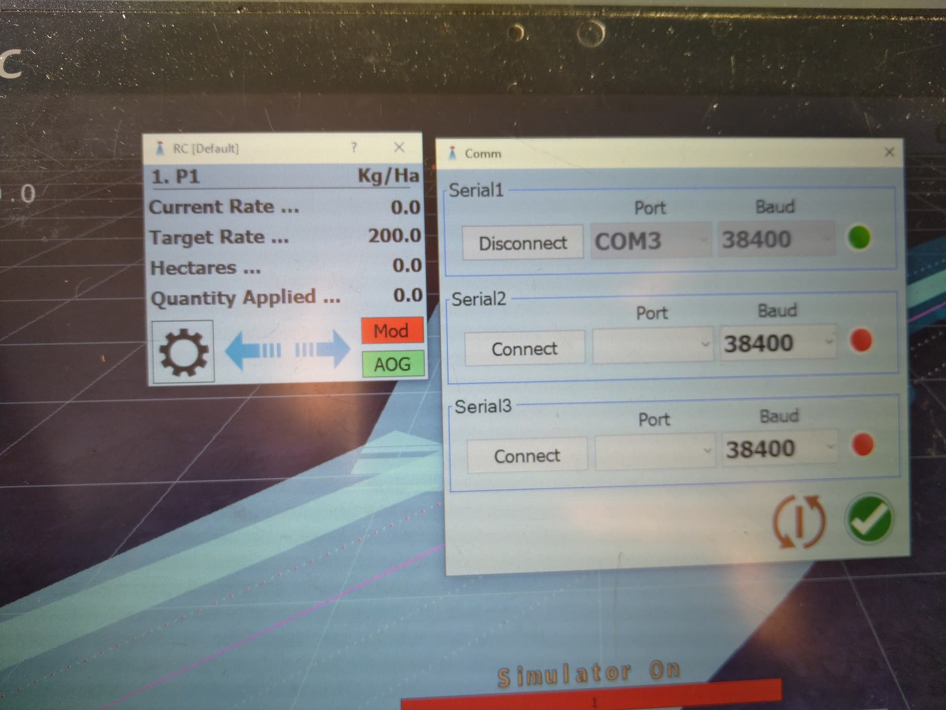
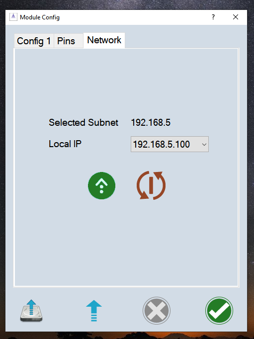
In Network - Local IP it is not possible to deselect Local IP address or make any change.
If i manage to solve this mistery, i will make a Youtube video with assambley and settings for sure
Change the counts/rev to 1 to see if rpm changes. Try just motor mode, not motor/weight.
Tried out RPM setting 1, no changes.
Found flash drive with old RC version from november 2023, uploaded that and Motor/weight works like a charm - motor revs lineary to driving speed, even above 6km/h, when new version Motor modes max out PWM.
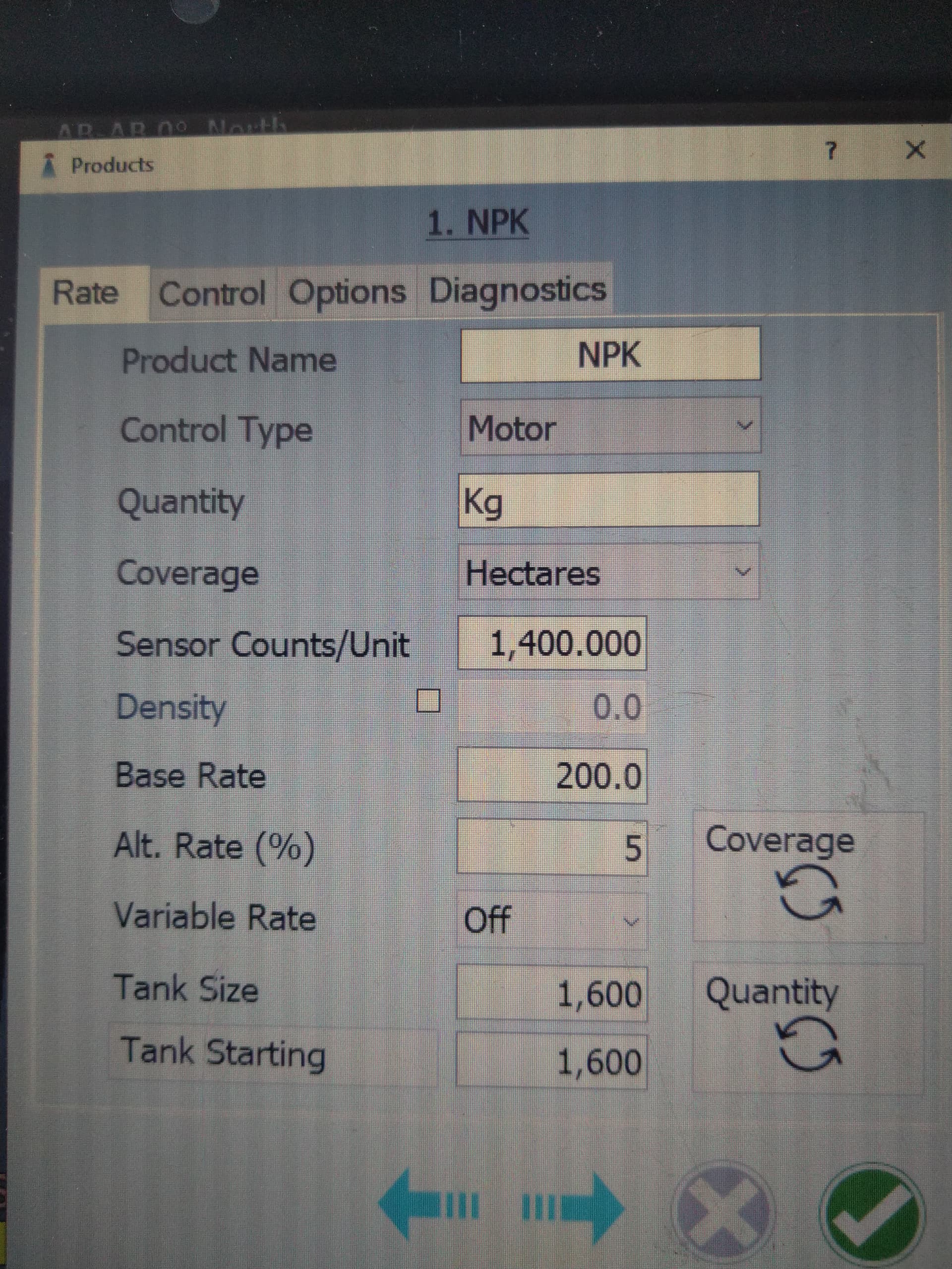
Motor/weight intended use is with a scale to measure the quantity of product being used. Do you have a scale? What does your product settings rate page look like?
No, i don’t have weight system (yet), but in that sense - does weight “signal” is still sent via D3 pin and actual motor RPM is not used?
Prop.Gain 0.5
Iteg. 0
Der. 0
Max 250
Min 10
Average Time pulse i have tried both options, but still the issue is funny. When stepping up speed at 6km/h it still works, but at 8 it spirals up to the max (actual rpm in diagnostics can’t get higher than 22rpm, even manualy turnig on motor to max 120rpm) and decreesing speed, it takes to drop to 4.5km/h to start function as intended. So it looks like it is encoder comunication fault. I added 0.1uF ceramic capacitor to signal, same as example PCB.
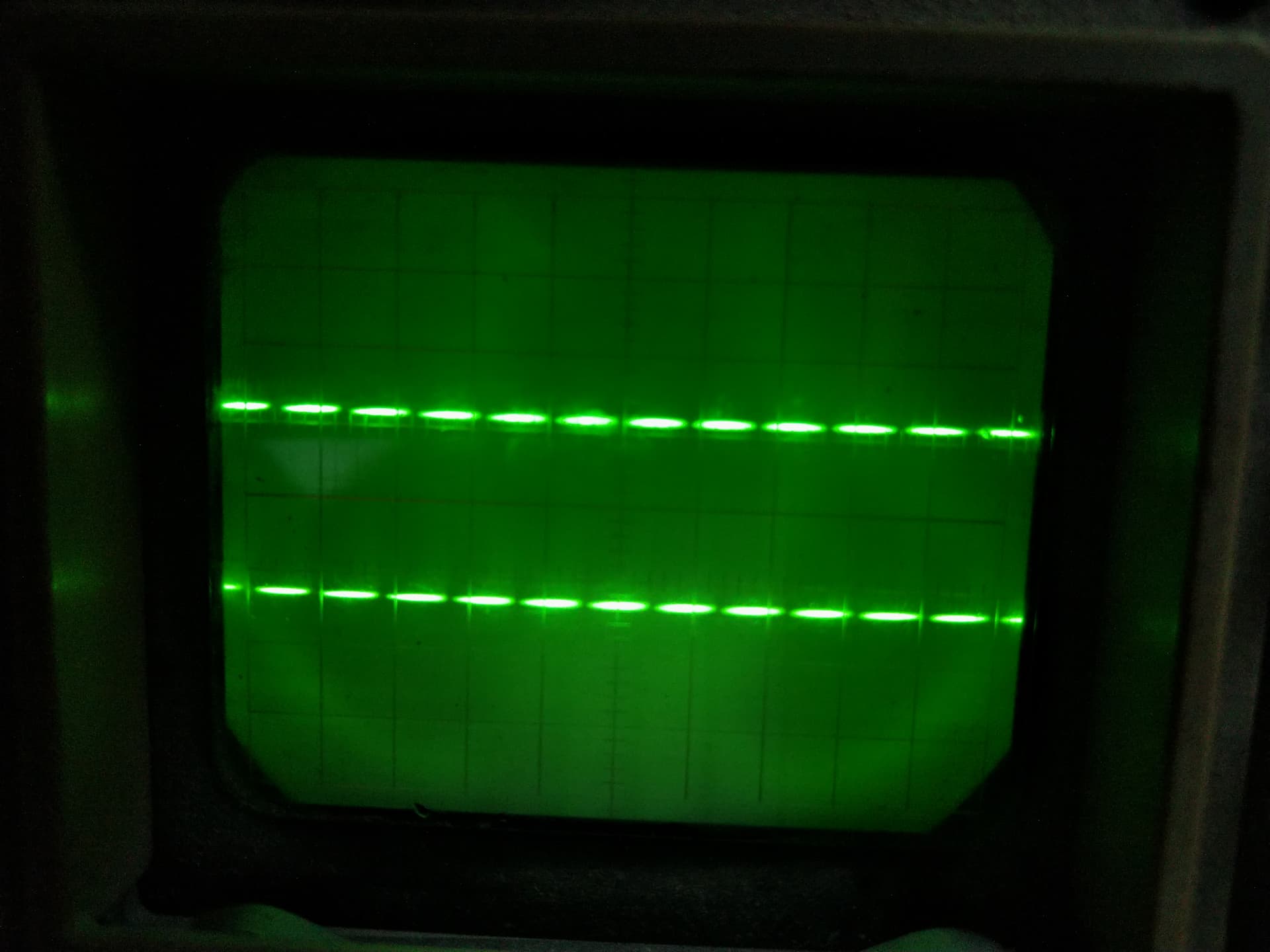
I even brought out vintage osciloscope to check signal
quality. I can’t messure actual time of pulse, but the setting is still in milisecond range, not micro. In the picture is signal at the max speed possible.
Encoder is OEM Servo city with dual output. It seems, that increesing speed, pulse lenght is not much degreesing, only gap (interuption) is getting smaller. Disconecting capacitor doesn’t affect sygnal.
Hi,
I have four scales and I want to use them to determine the flow of the product.
Which board should I use and how should I connect the four scales?
Thank you.
The use of scales is not finished.
Do you have a branch?
I can help you with the developement.
I plan on using 4 hx711 and 4 scales.
Is there a all in one PCB with manual toggle switches, relays and rate controller? Looking at replacing raven rate controller.
This one has relays and rate controller:
This one is a separate switch box:
Hi, I am part way through testing an electric drive variable rate setup on a seed drill.
No microcontroller setup or installed yet through.
I’m looking for ideas on how to test the cytrons and motors at anything other than full speed using the MA MB buttons? A way to mimic PWM input with pot or similar?
Thanks
I most defiantly am interested in weight code, I have a montag air cart that I would like to use your RC design on.