IC2 is needed to provide 5V. J2 is needed. It is a 3 pin male header. J3 is a 12 pin deutsch connector and is needed. It is strange those parts are missing.
The main problem I had with this pcb is to get the ethernet working. I couldn’t get it to work. The pcb will still work with wifi. In fact everything else worked except ethernet.
Hello everyone, excuse me if it’s a dumb question but I cannot find the files for the pcb, just 2 weeks ago this link https://github.com/SK21/AOG_RC/tree/master/Modules/Teensy%20Rate/RC11_PCB was posted but it’s not working now. Tried looking through the github but didn’t find the gerber files.
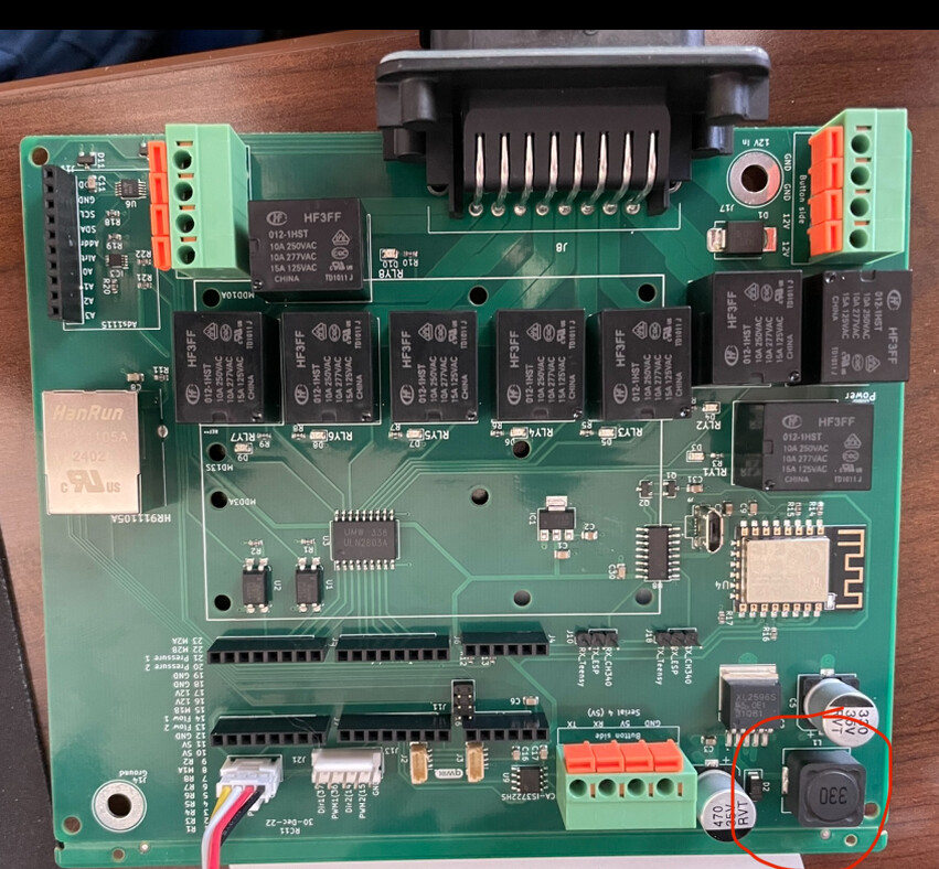
The 330 circled area gets really hot when powered on, I noticed another user posted (AgRate Controller - #2 by TeddyStamford) this board with theirs being turned with 330 oriented outward from the board. Which way is correct?
nothing connected, is powered on like seen in picture above. I am not sure where to start as teensy is programed and will flash orange when off board, but when I put it on the board it will not power on and flash. 2.7-2.2 is what it is reading on board in teensy power pin which it should be 3.3.
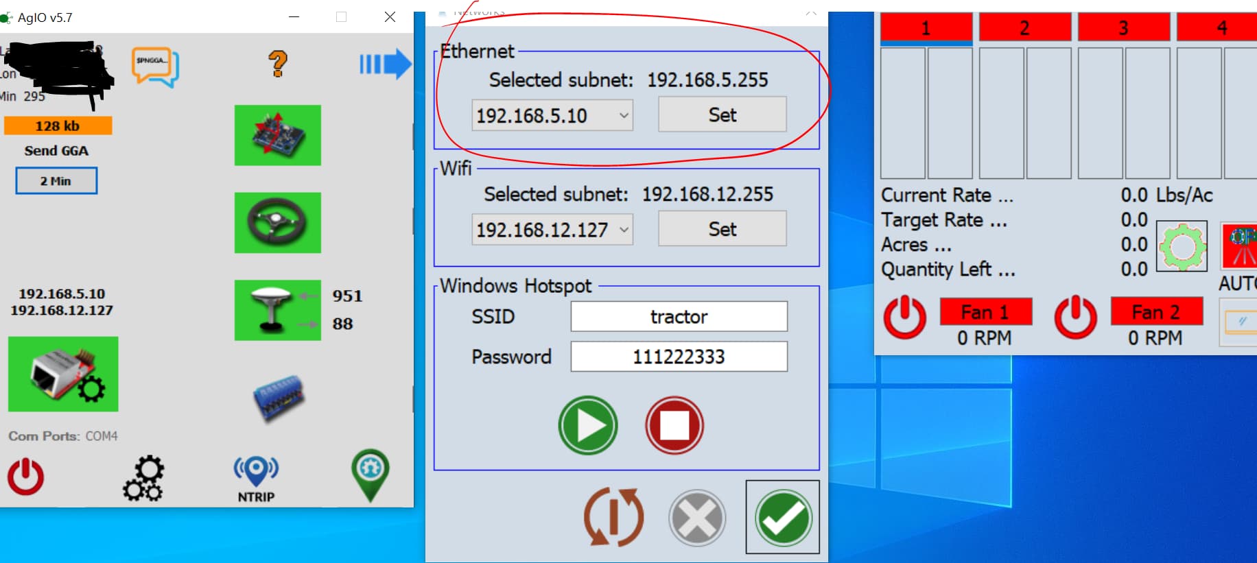
Could anyone share the settings/steps needing to be made to connect the RC11 board to AOG. I have tried usb and ethernet so far I can not get it to connect.