It would be great to have this speed simulation back.
We sometimes have to flush the system, which is basically operating it for 1-2 minutes with clean water.
What we now did is:
Close field
Close AgIO
Switch to simulator
Open a field
Drive at 10km/h
Open sections
Maybe our version is wrong but the calibration menu didn’t work when we were at the edge of the field.
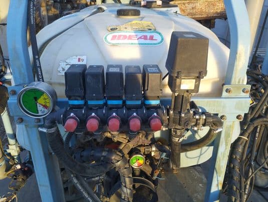
For these kind of valves that are somewhat common in europe we have no master switch.
Those sections are basically sending flow to either the tank or the nozzles. The turn knobs allow setting things up that when you “close” a section the pressure doesn’t fluctuate.
What this means from the RC point of view is we’d need the UPM for the full section width, irrevelant of the number of sections open or closed.
I wonder if this is something the system could handle?
We could also solve this by:
Send the actual % of the sections opened/closed. (I.e. we have 9 nozzles open out of 36 25%) then we’d know that the 12 UPM that we have is actually 25% of what we need to shoot for. So we can set our flowrate to 48UPM and measure 49UPM (but again send back 12.25UPM)
Is there a PGN with all this info so such hacks could be done?
Until recently, I had it so that the section relays remained switched on when the master switch was switched off. Then only the master relay went off and everything else stayed on. Now all the section relays are always switched off when the master is switched off. Has this been changed or do I have my configuration wrong somewhere?
I think it was 3.5.3, but I can’t really remember. I’ve only now had time to update the firmware of the Switchbox and the Nano to the new version. Was the programming of the rate controller app always such that all outputs are switched off when the master is switched off?
The master relay is supposed to turn on/off but leave the other relays as they were, either on or off. If no master relay then the master switch should turn on or off all the relays. This doesn’t work now with the master switch. It does work if all the section switches are turned on/off. I think it should just work with the master switch. I will try to fix it.
That is so perfect. The manual mode is now also better than before. Now you can also switch the master relay on and off even though no section is on. That’s just right, because you can preset the pressure manually via the main valve. Thank you !!!
We have a lot of sprayers with equal pressure system valves around here. If the master valve is off, it works, but if only a few valves are switched on, the calculation is incorrect because some of the liquid goes into the nozzles and the amount from the switched-off valves goes back into the tank. The pressure control can be adjusted well with the constant RPM. I think the only way to display the correct remaining quantity in the tank is to install another flow meter in the return line on the valve block and to recognise the pulses via the second ISR on the Nano and then calculate against them. Or are there other solutions?
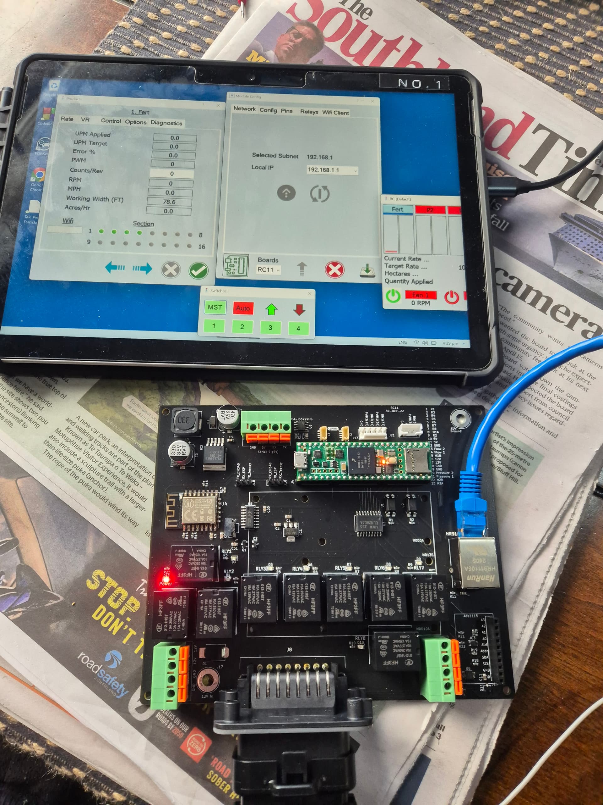
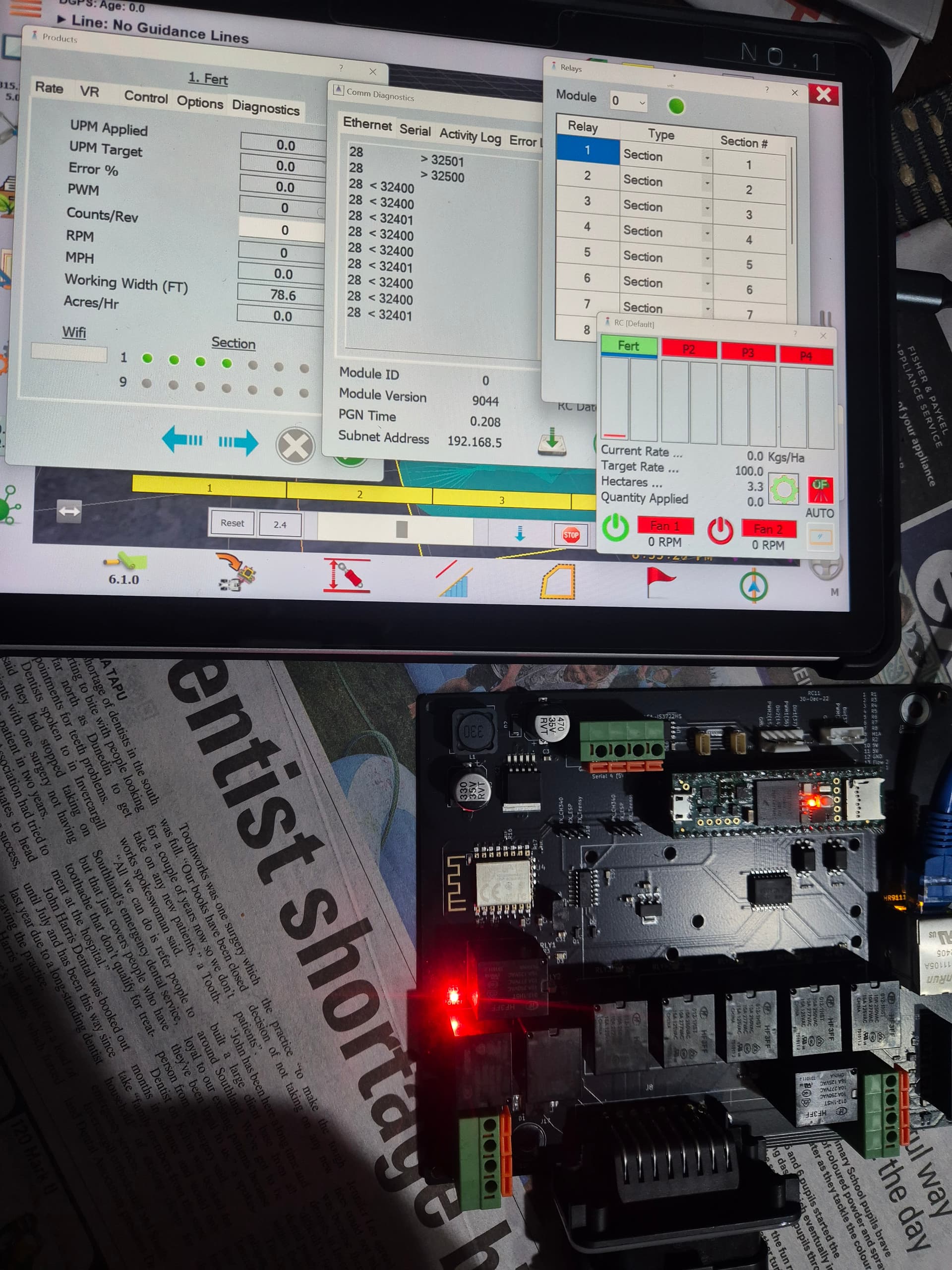
Does the Fert header turn green. In the picture it is blue. This means the module is sending data but not receiving. The subnet setting may need to be sent to the module. It is sent with the up arrow on the middle of the page.