Did you try resending the config data after the module header turned green?
Yeah that was the issue, thanks for the help ![]()
you have to adjust the flow proportionally so if 5 sections all equal and 1 section closed then flow is 80% of actual etc. I’ve not done it but I understand this is how manufacturers systems do it.
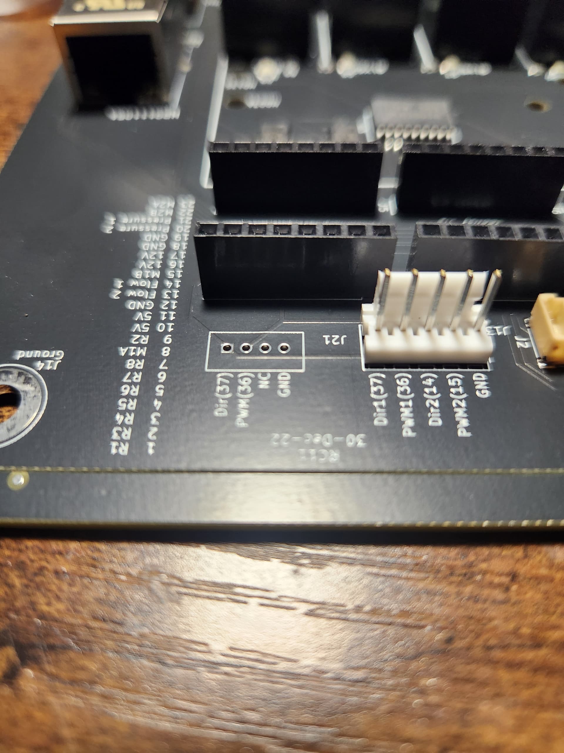
Having trouble to set up a RC12 board. Connecting the arduino via ethernet works fine. I do section control via relay driver. The problem Im facing is that if I switch on the sections the relays switch on but instantly switch back off. Im still connected to the RC12 arduino, but no switching is possible any more until i power down the pcb. It seems that the relay driver is having some kind of problem.
Maybe one thing to add: I have reverse polarity valves to control the sections, so I connected two relays to one IO pin. I also already tried to use an external power supply for the relays, but that didnt help at all. If there is no power to switch the relays (so the JD-VCC is not connected) the status leds turn on and off as expected. I am also sometimes able to switch individual sections on and off, but if more than 3 section are turned on it fails again
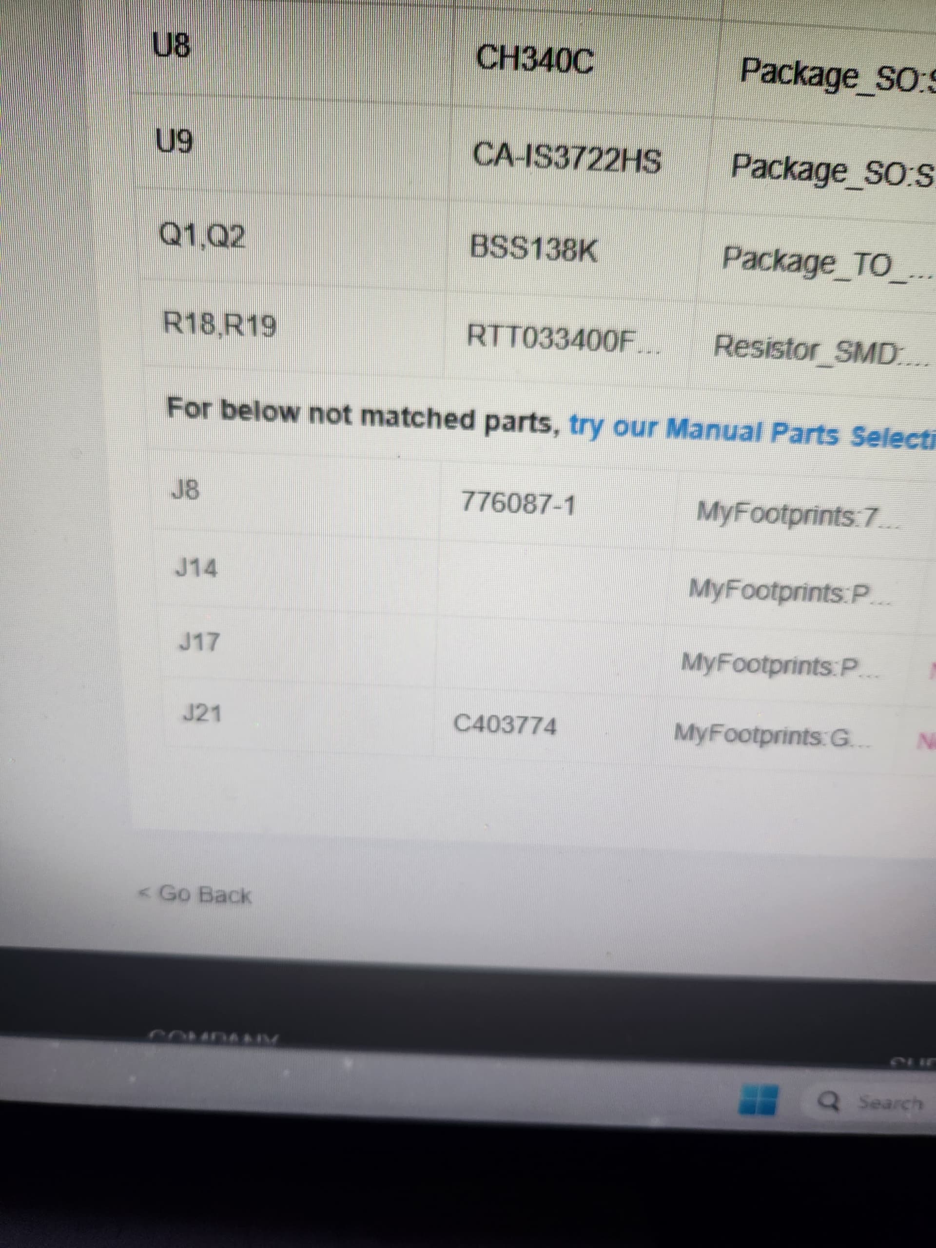
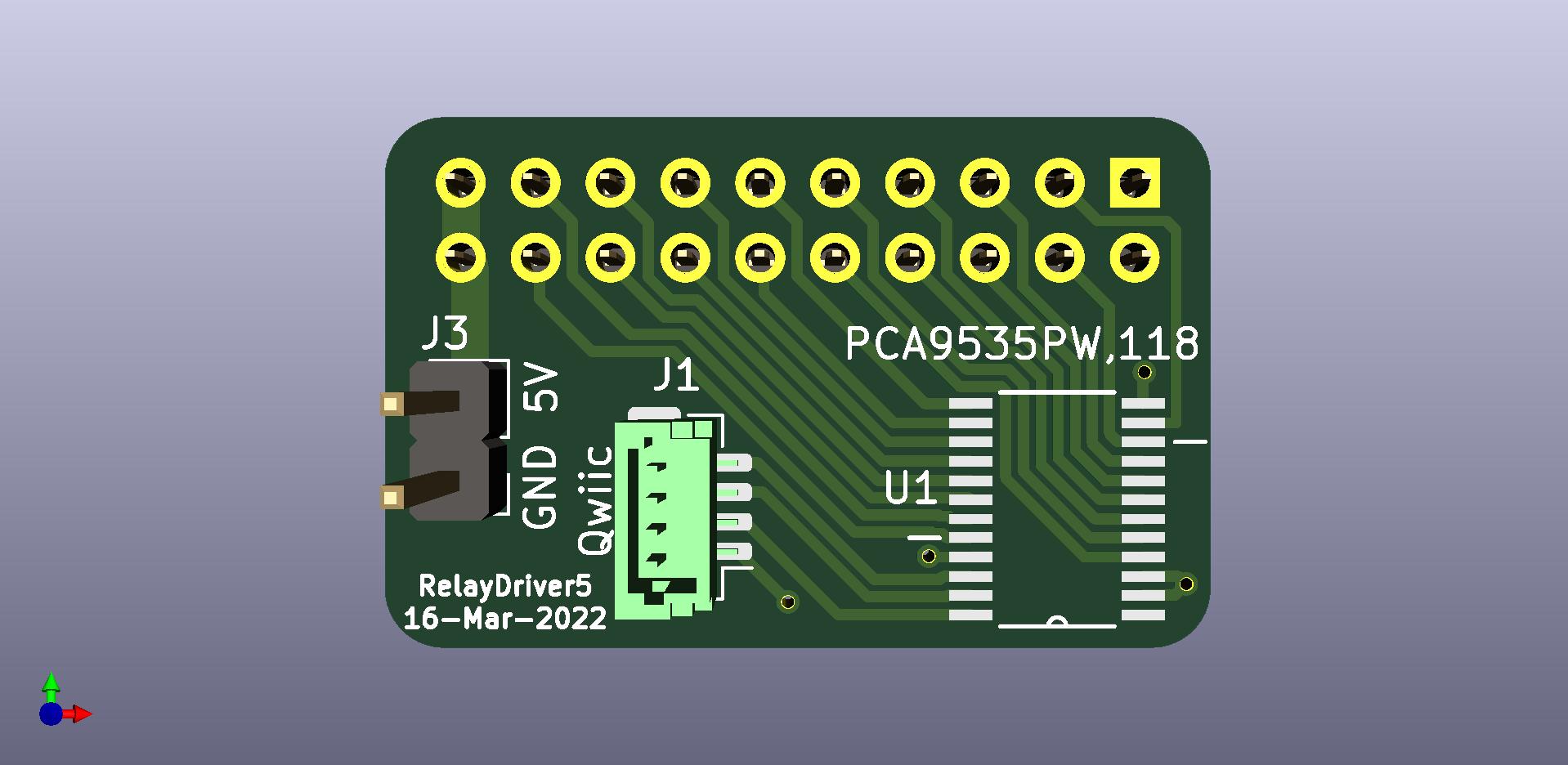
Are you using the RC12 pcb and this pcb?
How do you connect 2 relays to 1 IO pin?
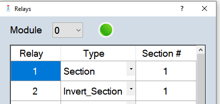
The relays can be defined in the app so when one is on the other is off.
Yes, thats the PCB. I made a little board to be able to use screw teminals for wires instead of plugging this pcb directly into an 16 way relay module, since I only need 10 relays. So i plug two wires into one io output of the pca9535. I just need two relays switching at the same time, no need for inverting.
And yes, im using RC12, with latest code
Does it work with only one relay for each IO?
I tried to wire it in as good as possible with one relay per IO. Still doesnt work, now its constant on/off switching of all relays. Looks like there is a short somewhere, will have to figure that out tomorrow or so and probably use a 16 relay module as the relay driver is designed for in the long term
I’ve got an RC11 board, connected a motor with an encoder, and while I can get the motor to spin in calibration mode, I’m not getting any speed signal from the encoder. In the calibration scree, pulses stays at 0.
The encoder is getting 5v, and with the motor spinning a multimeter gives the encoder signal as about 3.8v as it averages it.
I’ve got the encoder signal connected to pin 14 on the ampseal, and the P1 is set to motor with a sensor location of ModuleID 0 and SensorID 0. If I change either of those, the motor will not spin, and still no pulses.
U1 and U2 are both fitted and look to be the correct orientation to the PCB image.
Is there a setting I’m missing somewhere, or a way of testing that the signal is actually getting to the Teensy?
The pcb is providing 5v on the sensor pin and expecting the sensor to provide ground on each pulse to complete the circuit. Does the sensor show ground when not showing 3.8v?
It blows my mind. Its almost night.
I don’t think it’s switching to ground, it’s switching between high and low, neither of which appears to be ground.
The encoder is described about a third of the way down the page here
Someone else had this problem. I think they hooked up another opto that would switch to ground with each pulse. I am looking for their post.
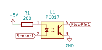
It is similar to the diagram in this post but pin 3 of the extra opto goes to pin 14 on the ampseal and pin 4 of the extra opto goes to ground.
1 Like
Ahhhh I see what’s happened here!
Post edited as may well be nonsense! Awaiting replacement part, as supplier is confident the encoder should work with the RC11 board.
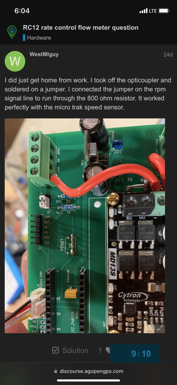
I don’t know if your referring to the conversation where I asked you about a pulse to ground flow meter, but I made mine work by removing the opticoupler and soldering a jumper in its place so the flow meter could directly ground out the pin on the nano. That could be what hallfarmbill needs also.
Yes that could help.
I’ve been talking to the supplier of the motor & encoder today who’s confident the encoder should work with the RC11 input after looking at the schematic. No output from the encoder though, so he’s sending a replacement, will see what that does.
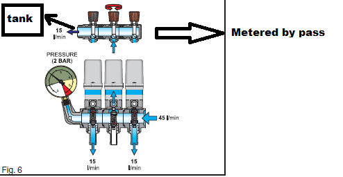
Are you talking about this? I wonder about this too, I think commercial systems can calculate this.
When the small adjustment valves on each section are calibrated, when one of the sections is closed, the pressure remains constant, but the liquid coming out of the closed section is sent back to the tank, the flowmeter calculates this liquid as if it was sprayed from the nozzles. How did commercial systems solve this problem?