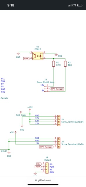
I have a question about flow meter hook up to the RC12 rate control board. I want to use it with a Micro Trak brand flow meter. The flow meter operation is similar to a Raven. The unit grounds out the signal wire every time the magnet on the turbine goes by to create a pulse. I can’t read flow with that flow meter. I looked at the schematic. I see the opticoupler is grounded to the board and it appears it is set up to see a positive voltage pulse instead of a grounded pulse. Is there a way to utilize a Raven/ Micro trak flow meter with this board?
Does it have 3 wires similar to the one used with a Spray-Mate II controller?
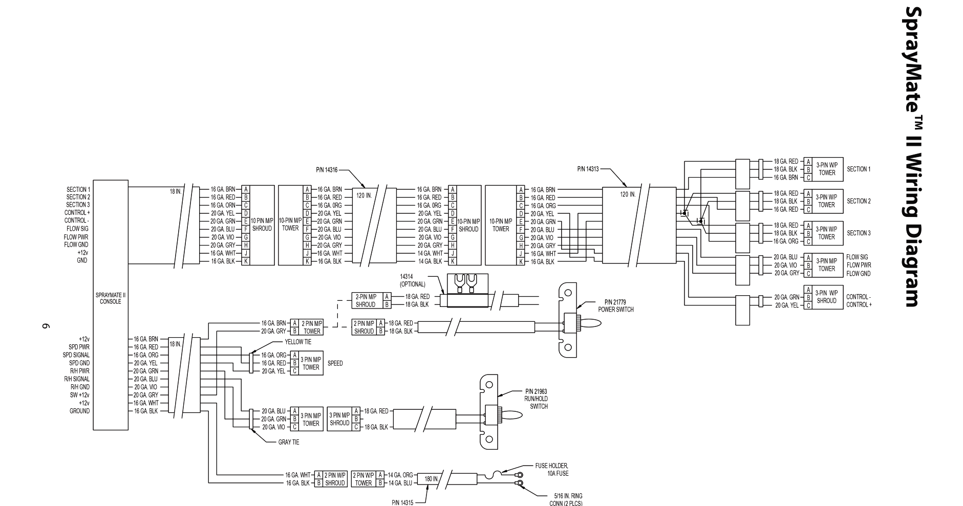
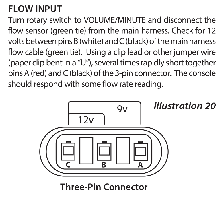
In the Spray-Mate II manual it shows how to trouble-shoot the sensor. It looks like it outputs a voltage.
I use one of these flow meters in my sprayer.
Wrote my own code and treated the pin as input pullup. I don’t remember off the top of my head and I’m not near the sprayer to test, but this tells me it goes low/to ground on a pulse.
For what it’s worth I do know it will work at 5volts, doesn’t actually need 12v to pulse
I have 18.25 pulses per litre written down here too.
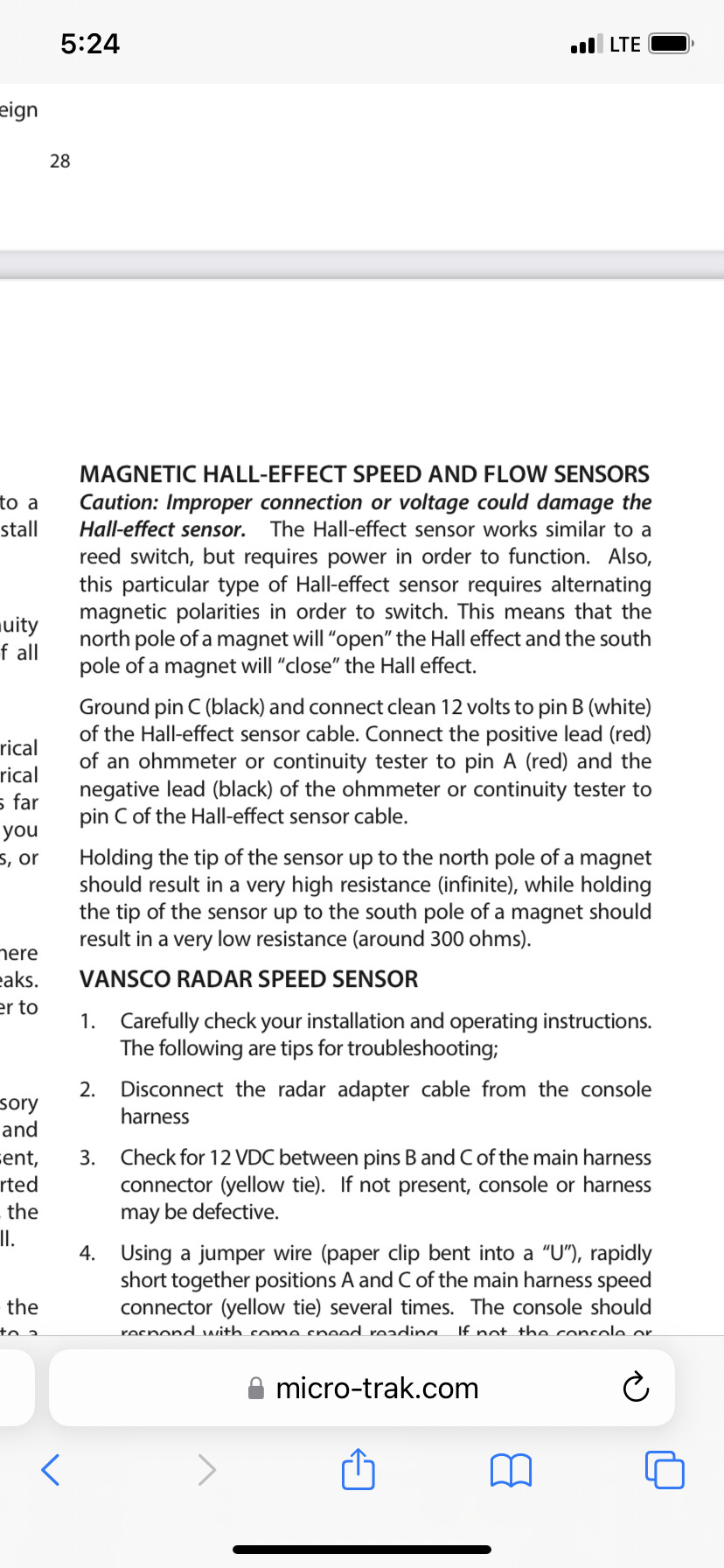
What you posted is the exact flow meter set up and cable I have. I tested the sensor last night and it performs as it should according to this test procedure. I get 300 ohms ground to signal with the magnet one way, then I flip the magnet over and get a resistance of 4.5k ohms between ground and signal.
What flow meter did you have in mind when the board was designed? If I am thinking correctly to make this style flow meter work the opticoupler would need a constant 5v supply, then the signal wire would then complete the ground circuit for a pulse.
I like the safety of the opticoupler, but in this instance with a low resistance of 300 ohms on the sensor to ground, do you think it would be safe to bypass the opticoupler and connect the signal wire directly to the nano?
Edit: I also thought about desoldering the opticoupler and putting in a jumper between pins 1 and 4. Then there would be a resistor in series for more protection.
Thank you for the info. I remember reading that sensor would also work with 5v
It was built for a sensor that provided power on a signal. Connecting pins 1 and 4 should work I think.
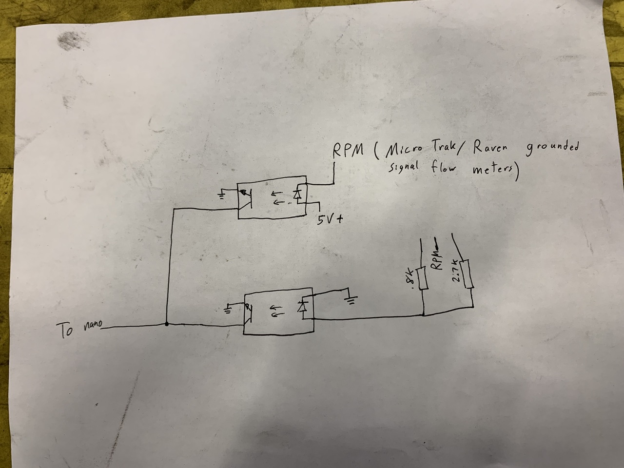
I’ll give that a try. One idea for future board redesigns, could a second opticoupler be added to the board in parallel for meters that pulse to ground? In my quick sketch below the lower opticoupler is what is currently on the board. If a second opticoupler was added next to it, that one could be connected to 5v power, then grounded through the flow meter. You could then have two attachment points for the flow meter signal wire. The user could then chose one for pulse to ground meters and the other for pulse to power meters. That would add a lot of functionality for Micro Trak and Raven flow meters commonly used in the United States and Canada.
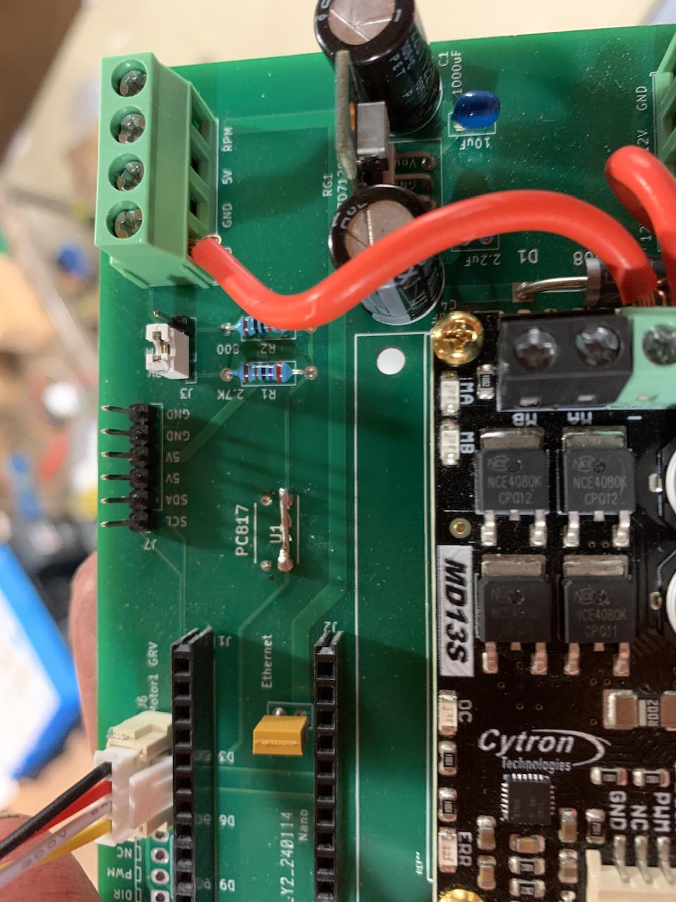
I did just get home from work. I took off the opticoupler and soldered on a jumper. I connected the jumper on the rpm signal line to run through the 800 ohm resistor. It worked perfectly with the micro trak speed sensor.
1 Like
That looks perfect on the board you have drawn up there. Thanks for the help
I am interested in this board for. Sprayer control as well. Does the cytron drive the flow control valve? Do you have a version that has relays for sections ?
The cytron does drive the flow valve. This board has relays: Rate_Control/Teensy/RC11_PCB at main · AgHardware/Rate_Control · GitHub
Is there a summary about all the rate controller versions?
So relays for the sections and room for a cytron to drive the valve and input for the flow meter. Kind of an all in one for my sprayer?
Or is the cytron built into the RC11_PCB
So when I upload the BOM for the RC11_PCB it says “REF designator doesn’t exist in the BOM file”
EDIT: I just ignored that and it went to the next step but there are lots of parts missing.
@SK21 was most of the components available when you ordered?
So RC15 seems to have most of the parts available. Is that the latest version? Looks like the drv8870ddar’s are instead of relays.
RC12 is a through-hole board that is self assembled and the least expensive. It can control one rate. It can be connected to a relay module with another small pcb. It uses a nano and a cytron.
RC11 uses a teensy and a cytron. It has relays. It can control two rates and eight sections.
RC15 uses an esp32. It has DRV8870 motor drivers to control two rates and seven sections.
The parts were all available when I ordered. It should be possible to make substitutions.
Thanks for that clarification @SK21
I guess I am not brilliant enough to make a replacement parts list @ JLC so I am shooting for the ESP32 board. However, my one question would be, if I am using the WIFI on my tablet for RTK corrections, can I still use this boards WIFI to communicate the rate info to AOG, as my WIFI is currently tied up.
Is the wifi from a phone hot-spot or from a router? The ESP board can connect to a wifi network. It can also connect to ethernet with a W5500 module.