You can get the connectors here:
Or use this cable with the existing connector on J13:
You can get the connectors here:
Or use this cable with the existing connector on J13:
Awesome, Thanks!
A quick update: Sections work now, using one pin per relay. Had to solder in a capacitor between ground and +5V to filter out some interferences (at least thats what Ive been told, no electronics expert) to make it work. Maybe something to consider if someone would redesign the relay driver pcb. Got the same problem as described earlier with no pulses from a polmac sensor, seems to work with a jumper instead of optocoupler. Is there another optocoupler model that might work with these sensors?
Hello, this is most likely an embarrassingly easy question.
I have been bench testing the Rate controller( newest version) with KenStuff’s adapted AOG for variable rate. When I open the Rate controller first and then open AOG and AOGIO I get a warning that “only one usage of each socket is normally permitted”, RC app functions properly other than the VR target never reacts to my Script (Always sits at minimum limit). If I open AOG first I get an UDPagIO failed start exception when I open the RC app.
Anyone have an idea of what simple step I am missing? And how Can I check the PGN Data to see exactly what is being sent ?
Polmac, read …
Are there any conditions that would cause the master switch to immediately turn off after activating? I can push the master, the valve will turn off for a second, then the master goes back to red.
Pretty sure the new rate app is not designed to work with the older version of Kentstuffs adapted AOG version.
You need you use the new version of AOG and depending on how you want to make your map some editing of AOG will be needed to make map transfer easier / possible.
Do you mean that the master is red, you push it, it goes green and then back to red? Do you have a switchbox connected or are you only using the on-screen switches? Is this the rate app switches or AOG switches?
As CommonRail said the rate app only works with the newest version of AOG.
Yep that’s exactly what happens! This is the rate app on screen switch (MST) I have a foot switch hooked into 5V and rte2, but I haven’t gotten it to function, so I actually turned work switch and momentary off under configurations.
What is rte2?
Thank you for clearing that up for me.
I had the momentary footswitch wired into rte 2, and a 5V output with pin 3 assigned to the work switch in the module config. I have since removed the foot switch a f disabled the work switch until I can get this system to work.
I seem to be experiencing some of the same issues you were with your RC12 rate controller. I also had issues with the relays clicking on and off when I first installed it until I ran a separate power wire for the relays and the RC12 board. I am having issues occasionally when the relays turn off on the headland, they won’t turn back on again when I get on line and leave the headland. It sounds like I may also need to add a capacitor to my 5v power supply wires going to the relay driver. Do you know what size capacitor you used when you added it?
actually i soldered in one 100nF condesator and one 47uF electrolytic condensator between ground and +5V. Do you have reverse polarity valves? In my case one of the motors was missing a condensator too, that caused additional trouble. Now it all works like a dream.
I had the relay driver redesigned with both condesators and just ordered them from jlcpcb, cleaner than soldering the condensators to the wires
Another question @SK21:
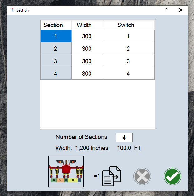
is it possible to assign specific sections to the switches of the switch box? I have 5 sections and would like to control the outer ones with physical switches (sections 1,2,4,5), but found no way to tell that to the rate control program.
And one feature request: It would be cool to have some on screen buttons that can control individual relays, eg for work light of the implement, maybe even with interchangeable names for the button
Use the section dialog to change which switch controls which sections.
How many extra buttons would be needed? Maybe a group of 8 buttons that can either be section relays or other relay controls.
v6.3.0 for testing VR and section control.
v6.3.0 for VR and section control testing.
Notes:
yea 8 would be plenty, for me it would be ideal to be able to use them instead of section relays with the relay driver, following your structure with the dropdown menu to select what the relay controls. Would be cool to be able to name the buttons somehow, dont how how easy that is to do
Thank you for getting back to me. My sprayer has solenoid valves for the section shutoffs. I noticed my issues seem to be when I would have all the sections shut off at once. I added diodes at the solenoids to suppress the voltage spikes. Everything ran perfectly.
Thank you for all the help getting my rate controller working. Saturday I wired in some diodes to suppress the voltage spikes when the boom solenoids disengaged. This took care of my final freeze up issues. The voltage spikes must have been causing issues for the nano. It makes spraying a breeze now with auto rate and section control with auto steer. One final question, I saw an option for a pressure sensor in the app. Can that be utilized with an rc12, or is that for use with different rate controllers?