Good that it is working for you. The pressure sensor works with the RC11 or RC15 that have an ADS1115 to read the signal. Do you have a diagram for the changes you made? It could help someone else that might have the same problem.
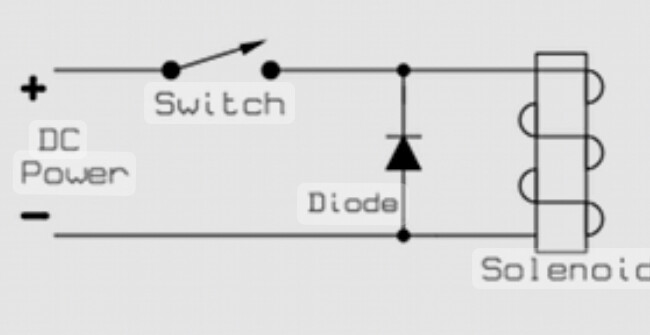
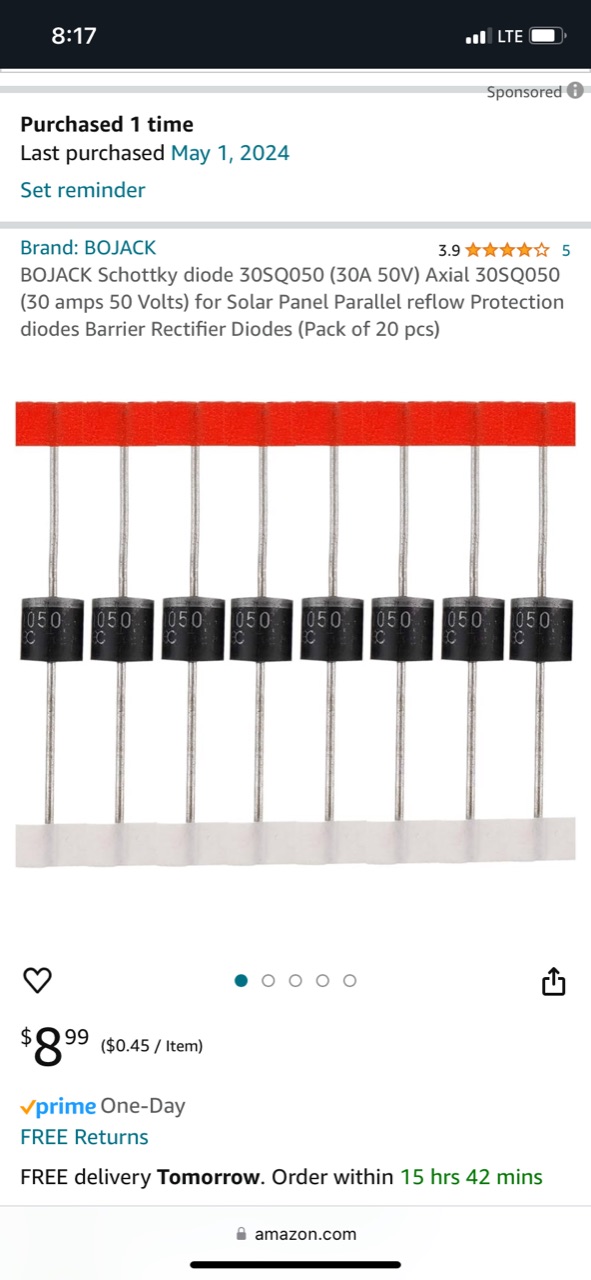
Good idea. A quick summary of what I did. When I first installed and began using the rate controller it worked well, but the nano would freeze up if all the boom sections were shut off at the same time, or if I was in automatic mode and the boom sections were rapidly turning on or off to cover small areas. My sprayer has 3 solenoid valves, one for each boom section. I began to suspect voltage spikes from the solenoids deenergizing may have been the issue. I initially ran one power wire to the rate controller and branched off another line to power the relay board that controlled the sections. I then ran a separate power wire to the rate controller board and another power wire to the relays. This seemed to help a little, but I continued to have issues. I then added suppression diodes to the solenoids to dampen the voltage spike of the solenoids deenergizing. It is recommended to select a suppression diode that is 10 times the amperage rating and 4 times the voltage rating of the solenoid. My solenoids operate at 2 amps/ 12v. I bought some 30 amp/ 50v diodes off of Amazon. I wired them into the sprayer harness right next to the solenoids as shown in the attached picture. The silver blocking end of the diode should connect to the power wire from the rate controller relay board and the other end to ground. After adding the diodes my freezing issue is resolved and everything works great.
1 Like
Hello, actually the locking of the nano here is not due to voltage failure but due to reverse EMF. When the coil energy in the solenoids is cut off, it creates a reverse electromotive force, which affects the semiconductor components before the coil, the processor and causes it to lock. The diode you will use does not have to have a high current value, it is high. It is more important that it has a voltage rating, for example 1N4007.
When the electric current applied to the coil is cut off, the magnetic effect on the electromagnet does not disappear immediately, and with a reverse effect, it uses the coil as a generator, creating a high voltage in the opposite direction at the ends of the coil.
This reverse high voltage can damage the transistor or microcontroller driving the coil immediately or in the long term.
That’s why we connect a diode in reverse to the coil and eliminate this reverse voltage on the diode.
1 Like
I thought the relay module would have protected the nano from the voltage spikes because it uses optoisolators.
I am far from an electrical engineer, but after I installed the diodes I wondered if I could have accomplished that same thing by providing the coils with a constant 12v and then using the relays to complete the ground circuit to engage a boom section. Then when a section turned off the voltage spike on the ground wire would be isolated from the rest of the system. Maybe I am way off in my thinking and feel free to correct me, but I wondered if that would also be a viable solution.
I wonder what could / should be done when controlling solenoids via motor drivers (e.g. TB67H451FNG ) ?
Here’s our current schematic:
Motor driver A / B → green/red diode to GND which show if they’re on. So essentially:
A → LED → GND
B → LED → GND
Now when this is is used as solenoid driver we only connect let say A and put the other end of solenoid to GND. Based on the above schematic we should also add a diode that goes from GND to A ?
Or because technically the motor driver goes to GND when switched off that would close the loop?
What do you suggest?
Here is a test branch that has 8 on screen buttons. The buttons can be renamed and can control individual relays. This is setup on the Options dialog.
3 Likes
From a first quick test it looks like what I was hoping for, thank a lot ![]()
Would it be possible to use more switches with the switch box to coincide with the updated test rate controller app? I have another sprayer with 5 sections. It would be nice to have a switch box with 5 section switches for that sprayer.
The app can use up to 16 switches. The switch box code can do 16 switches as well.
Thanks for the clarification
Sorry for my late reply, if you are talking about controlling a solenoid valve with the motor driver circuit (TB67H451FNG), I have never used it before, but it can be used, I have always controlled the motor with the motor driver board, the reverse diode I mentioned should be used if a voltage comes from the relay to the solenoid, and to protect the circuit. , as well as to prevent crashes and resets. However, if a dc motor is used, this diode is not connected, because the diode will short circuit as the motor will change direction.
I’m sure it something simple I’m missing but when I try to upload the gerber for the teensy RC11 board to JCLPCB it doesn’t have any components for assembly. Anyone have a similar problem?
I’m using an RC11 PCB to control the metering on a seed drill, rate control all works well, but I want the motor to stop turning when not seeding, ie turning on headland, when stationary, passing a previously covered area etc.
But, despite trying all combinations of settings it keeps going. I have just one section.
So, I’m going to fit a relay, on one of the motor wires ,that will be switched by the section relay.
Before I do, is there anything I’m missing?
Just tested the code again and the motor shuts off on headlands, stationary etc. Is the control type set for motor? Is a valve used to control the motor?
1 Like
Thank you, so knowing it should work as I thought, I found I’d set a min UPM,
Putting that back to zero fixed it.
1 Like
I’ll add that fix to the troubleshooting Wiki page.
2 Likes
Thank you @SK21 rate control app and RC11 worked like clockwork all day metering seed for a Broadcaster

Super accurate ![]()
6 Likes
@SK21 sorry for the message in the wrong topic. I wired another rc8 board and switch board. Using ethernet, everything works except the cytron for the flow control valve. Manually the buttons move it. The inc/dec switch does nothing, any ideas? The switch to the arduino is getting signal, then from there to the rc8 arduino I’m lost!