Not set the colour yet, but exported boundary and shapefile as image (png).
Then aog dont open the field.
How do aog open a png field?
Not enough clear that part
Yes I did. I managed to get connection trough router on wifi, but then relays don’t work. Followed your instruction video’s but cannot get connection yet. Try Tuesday evening again…
this is the test file
elcar1321.zip (21.2 KB)
- Make a new field from KML
- Click “Spanner/Hammer” Click “App Map”
- Click the Map icon, then click the % icon, then click the green tick.
- Close the field
- Open your shape file in QGIS, close all layers other than your shape file
- Make the rate based on the red, make sure green is zero (unless you what that section off). Also make the lines the same color as the area.
- Export the image based off the shape layer and add some resolution (150dpi ish) , navigate to the AgOpen field file and replace the file “RateMap1.pgn”
- Reopen the field in AOG and your filed should be there
Notes:
You will have to use the modified AGO in the link above as it loads the image based off the boundary.
The standard version will not load the image size correctly.
The option to just click “Load Rate Image” button is work in progress.
Thank you for your time.
Im not sure, which modified AOG, is the correct one.
Could you be more specific .
A few posts up (Post 938) I linked a post in another discussion. In that post there is two items 1 is the modified AOG, the other is a video of how to make and load a basic image
thank you!!
Hi all,
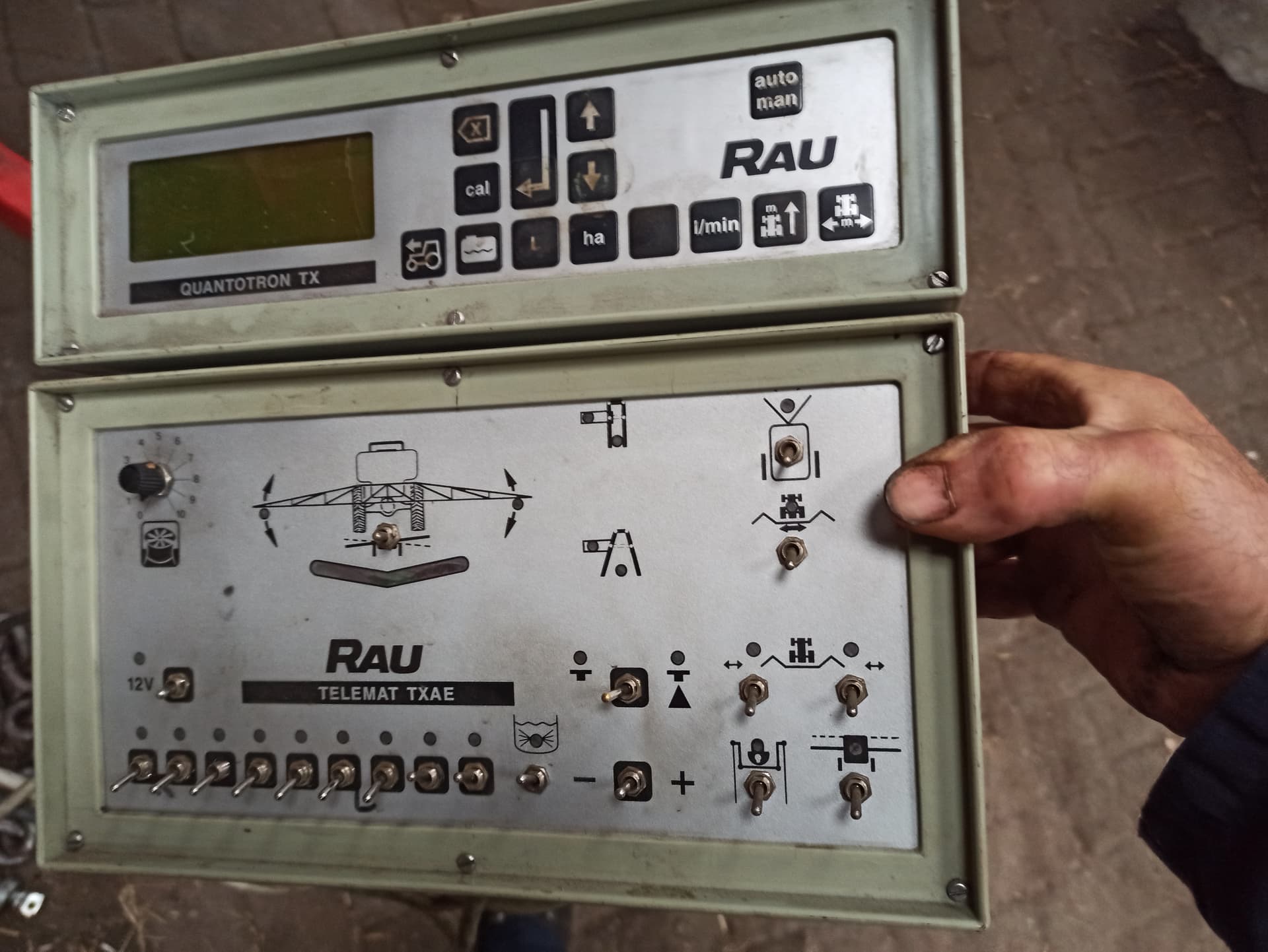
I’m try to adopt the AG_ASD_ESP Sketch using ESP32 board to make it working with version 6 without any success. The Rate app is not able to see the modele even using the Wiki or the USB/Serial. I would like to use the great Rate application done by @SK21 able to read the variable rate data coming from the AOG V.6.3 made by @CommonRail. Could you please help me to understand witch update need to be done to make it working with Rauch Quantron A (RS232) Monitor?
Thank you very much in advance.
So I managed to get connection AOG to RC11. Still playing around how different buttons work. I want to replace my spraying computer and switchbox for this RC board.
Control of the boom already is on an external joystick. A few questions:
- can I let the air-blower work on different levels?
- can I use switch mix/no mix in tank? (think just 1 relay, have 7 sections so 1 left)
- can I use pressure switch manuel or automatic, the applied l/ha is controlled by electric pressure-adjuster?
I think it can be done, it is quite a learing curve for me. When I build a switchbox for manual use will AOG paint the worked area?
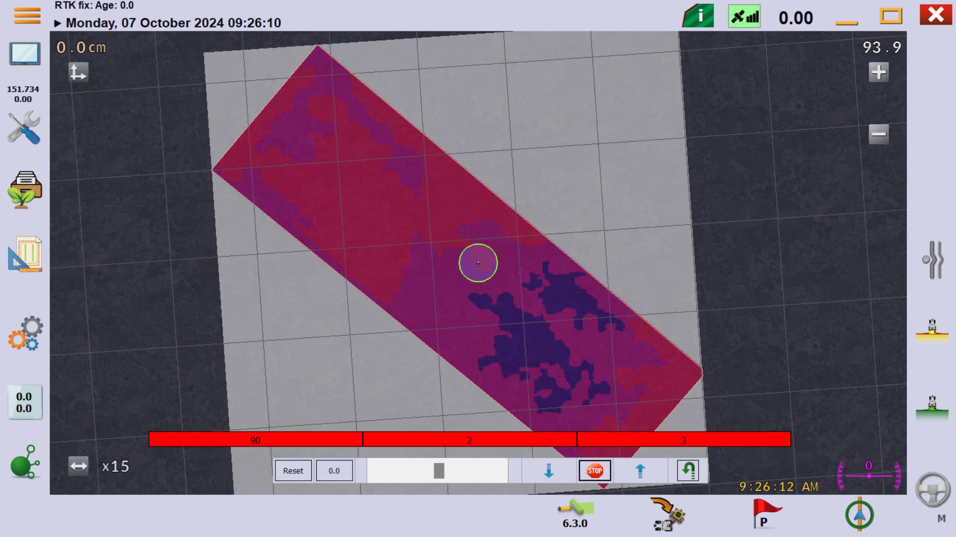
On the screen below I see switches 1 to 4. what are they used for?
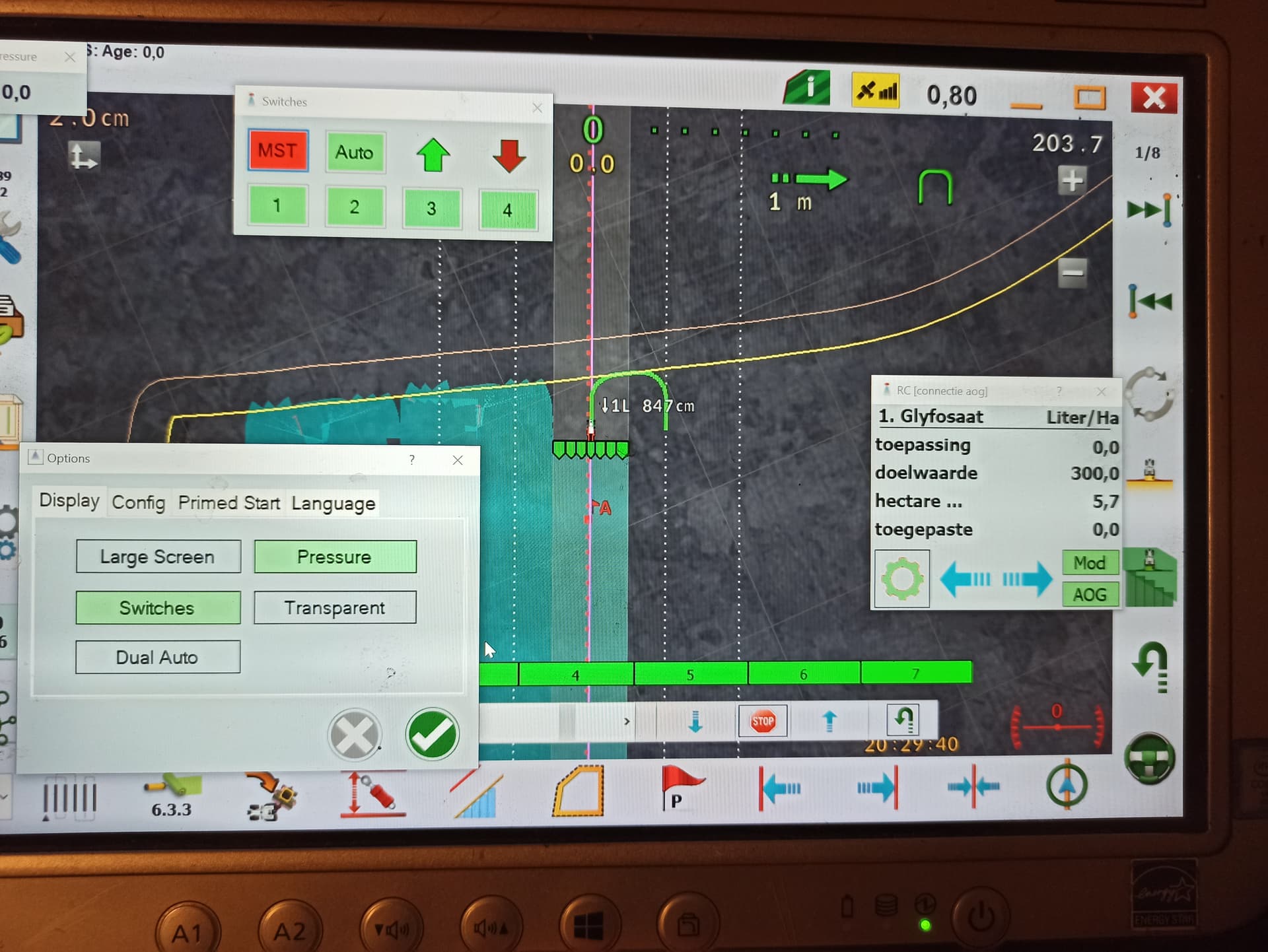
Switches 1 to 4 are for boom sections.
sorry, no questions left for now
Hi,
If you find something, please let me know, I’m interested too.
Is there a version for 7 section boom? Saw a video somewhere RC had 8 sections.
Where to find? Github?
You did spayer with rc11. Are there physical switches too for manually spraying?
Yes @SK21 GitHub here:
I still have my sprayers control box I can plug in if needed, but I haven’t used it since installing the RC11.
1 Like
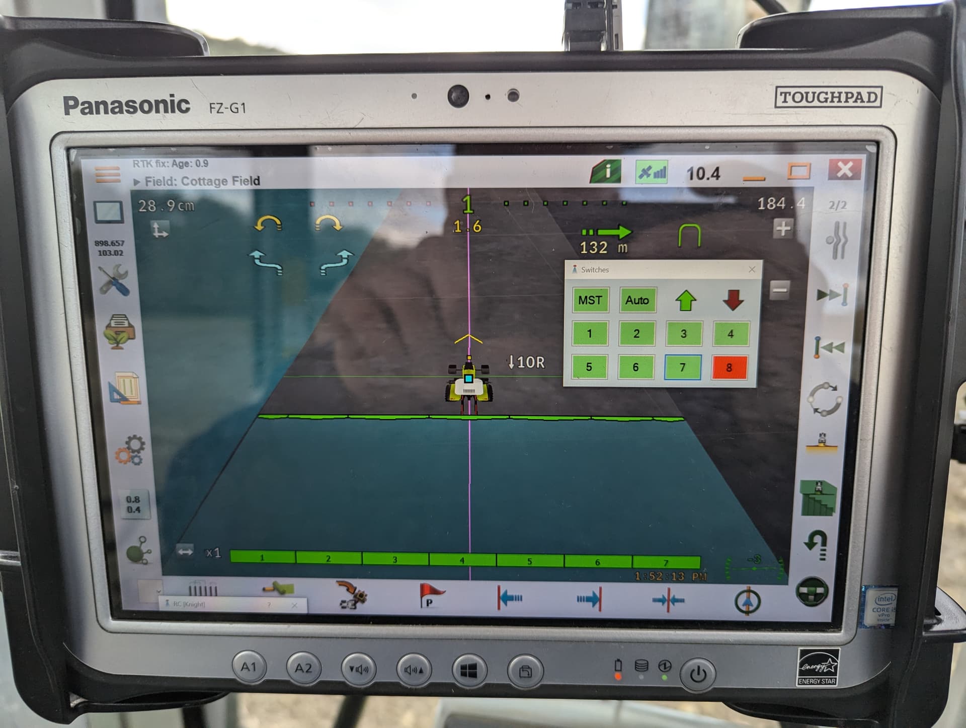
I have got the rc11 board, playing with simulator. Cannot get my 7 sections in switches, shown are only 4. And these switches don’t work in simulator? Should I make a change in .INO file to get 7 sections?
rc11 looks very promising, I am done spraying this season so if I have enough fate in it I start installing the board to the sprayer.