Yes you can use up to 8 boards. This is untested though.
Thanks, I’ll probably try it.
Thanks - that makes sense for the master relay. I think I can use a DPDT latching workswitch and power my LED that way. I just have to do some testing to manage the potential conflicts with the screen buttons, which I understand is why you designed the master switch to be momentary.
I did try the new colour options, but being boring, ended up with the v3.7 pattern!
Hello
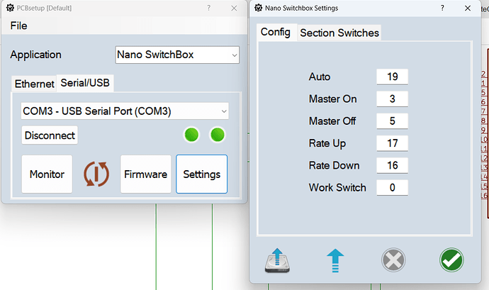
Is it possible to use the switch box from SK21 in AOG to switch the sections only for recording? I have recreated the box on the breadboard. But I can’t connect it to the tablet. I uploaded the code using PCBsetup.
I don’t have an RC board yet.
Are you using the rate app with it? If you are using ethernet you may need to set the subnet address from the app.
Yes, I had opened the rc app. SW2 was permanently connected to gnd. Then I tapped the two masters alternately to gnd.Videos
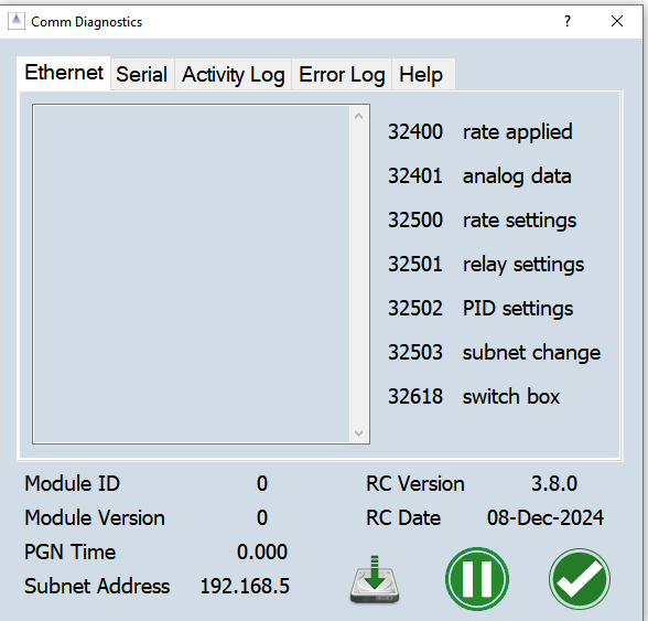
Check on the Comm Diagnostics page to see if the switch box is connected. You should see pgn 32618 in the ethernet window. What version is the rate app?
Bring up the ‘switches’ window on the RC app. It helps a lot to see what’s going on, though you can’t do anything on that panel if switchbox is connected - another check.
The switch box does not appear on the diagnostics page. It is the 3.8 version.
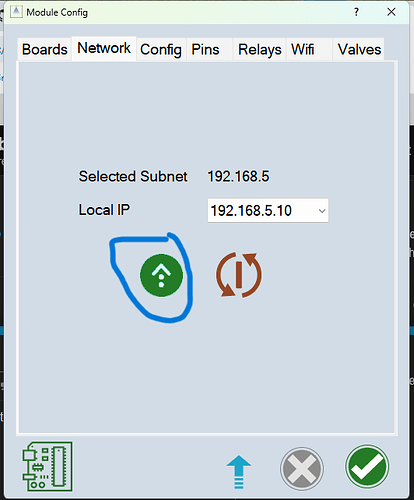
The IP of the switch box is 192.168.5.10. Is that correct? I clicked on the green arrow under Network. Do I need to do anything else?
Otherwise I need to try a different Nano or a different Ethernet Shield.
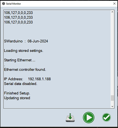
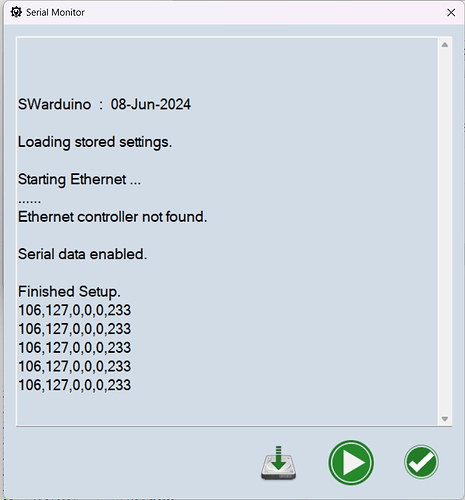
That should be all you need. You can also check the serial monitor in PCBsetup. You may need to disconnect and reconnect after uploading the firmware.
Thanks for your reply. The Ethernet controller was not found. I will try a different controller and a different cable later.
You don’t already use 192.168.5.10 for the computer?
That’s the IP I typically use😅
Have you checked you haven’t got the short on the ethernet shield?
First of all, I wish you all a happy and successful new year. Thank you for your support. I tested the shield with the multimeter. That doesn’t seem to be the problem. The message “Ethernet controller not found” still appears in the serial monitor of the PCB setup. At this point, the Arduino is connected via USB. Is the problem more likely to be with the Arduino? I tried two different Arduinos.
erything works now. No idea why, but it works ![]() . Thanks for your support.
. Thanks for your support.
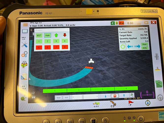
Quick question about relay control. I have a spare tablet I use for bench testing. I just updated it to v6.4.4 AgopenGps and just installled the newest version of the rate control app. When I have switches on the screen they don’t work to turn on the section relays. The relays only turn on when I press the automatic section control button on the right of the screen. Is there another setting I missed for the on screen switches. When the rate controller gets installed in the tractor, it will be run by the external switch box.
Do you mean the sections won’t turn on or actual relays connected to the sections?
The relays and paint on the screen. I have an rc12-2 board connected to the tablet and a relay board connected to the rc12-2. It worked as expected when I put it together. The on screen switch box from the app engaged painting on the screen and turned on the relays. I had version 5 .8.3 AgopenGps and a one year old version of the rate control app. When I updated AgopenGps and the rate control app, that’s when I lost the ability to switch paint and relays with the on screen switch box. The relays work as expected using the manual and auto section control buttons on agopengps
What are versions of rate control and aog are you using?
I have AgopenGps v6.4.4 and rate control 3.8.1
