And i have a 3 wired polmac flow meter witch has to powered with 12 volts. Is it possible to use the signal on a rc 11 board. Maybe with a resistor between ?
Do you mean a momentary signal to control the relays? Why does a constant signal not work?
1 Like
In that project i only need the section control to open and close the sections on a sprayer computer. And i can only do that by sending a pulse to an input on that computer. So i need an output pulse from the rc 11 to open and close the sections on the spayer…
I am testing. All th valves are working. I have connect a pressure control valve to m1a and m1b of the cytron. When i use the buttons on the cytron it works. But Is there an option to test it from the rc app by hand ?
Yes. Use manual mode and the rate up/down switches.
Ok.it is working… Master switsch has to be on. Thanks!
Just wondering if you would care to share some details on your project? I’ve been trying to piece together a system in my head for a planter system like this. I have the RC15 boards. I’m assuming you are doing individual row unit motors? Are you using steppers with integrated drivers? Thanks!
I spent a little time trying to make a stepper motor drive work. I didn’t get it figured out. I would like to revisit it next winter. I am not proficient in programming, but I am learning. For this year I went with an easier solution. I bought a 24v mobility scooter drive motor of of EBay and mounted a sprocket on it. My plan is to mount this above the planter seed drive transmission. Then I will run a chain down to a sprocket on the top shaft. That way the planter is still unmodified if I have an issue, I can just put the transmission chain back on and go to ground drive. I am running the motor with a RC12-2 board. I went to a 20 amp cytron motor driver rather than the 10 or 13 amp cytrons the board is set up for. That way with a 24v power supply I can control a motor of up to 480 watts. I sent feedback to the rate controller via a proximity sensor positioned to pick up the teeth on the sprocket sending pulses back to the board. I made some test variable rate maps and bench tested everything and it worked well. I would still like to try to set up individual row drive motors. I’ll see how the variable rate drive works this spring. If it works well I may just end up putting row clutches on the planter and calling it good. Just running out of time to pursue individual row stepper motor drive.

2 Likes
That looks like it will be a pretty slick setup! I’ve got a lot to learn myself. I haven’t ever messed with electronics like this. I’m hoping to just pretend it’s a pwm sprayer but use motor drivers in place of nozzles and can hopefully figure out turn compensation. Thanks for sharing!
https://talk.newagtalk.com/forums/thread-view.asp?tid=707537&DisplayType=nested&setCookie=1
Maybe this thread from newagtalk will help. Haven’t looked into a lot but it appears the stepper motors have an internal driver that can be controlled via PWM. May not require much if any code modification.
If you have success setting it up please share. I had a redneck setup that kind of worked on the bench. I took the PWM signal from the rate controller. I feed it into a digital to analog converter to make it easier for the arduino to read. The arduino then output a pulse per second signal to a stepper motor driver. I tried to have it put out a second PPS signal on another pin for feed back to the rate controller, but I couldn’t make the feedback work right. I think with more time I could get it to work. I am not much of a programmer, but I was able to make some code with Chat GPT and some code borrowed from some examples to build a planter down force monitor this winter. Chat GPT code doesn’t always work the first time, but if you keep telling it what the problems are eventually you will get code that works good.
1 Like
Thank you, that is some good reading on a similar project
Question about connectivity. I have fzg1 on havis dock. Fzg1 and havis both have lan port, but fzg1 lan is used for pcb. My fzg1 is connected to my mobile hotspot via wifi for corection. How can i connect rc15 to tablet? Rc15 is in cab, can i use usb? Lan to havis dock? Or it can be done over wifi somehow
I use an Fz-g1 and a Havis docking station in my machines. When you place the tablet in the docking station a new Ethernet port should appear. You will have to configure that new port that appears in the network settings with the correct IP address to go through the docking station. I have my tractor set up with an Ethernet switch, I have an Ethernet cable from the docking station to the Ethernet switch, then the switch has cables going to my steering control box, rate controller and switch box.
Do you have some more info about that motor ? I am also looking for a motor to drive a seed axel from a seeder.
I was looking for a cheap powerful gear reduction motor to try. I found lots of used mobility scooter motors on eBay used. The one I have is from a “Jazzy” brand scooter. It is a 24v motor that has a max output of about 120 rpm’s. I don’t know the specific model of chair the motor came off of. The only tricky part is most of those motors have a 17mm shaft. I was able to find a taper lock sprocket hub for a 17mm shaft to mount the sprocket
On my Dell Havis it needs 19v power before the Ethernet port shows up.
Can this software work with lh5000 protocol fertilizer?
I am thinking about ordering the RC15 board. However when I go to JLPCB and upload teh gerber bom and cpl file and go over to component placement I see that all components are in the wrong location. And some have been turned sideways.
Is there we fixed CPL file somewhere?
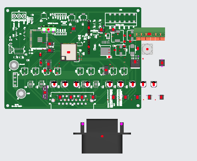
Also 4 components cannot be found. C10 C12 and J5 and J6.
The J components I guess are not important? The C components I cannot seem to find.
Also what other components will I need to control a seeder with this board? I would guess just a motor to control the metering unit?