Yes its working now. But i think the problem was that with testing on the bench there was only rc11 ont he ethernet and agopen on simulate modus. But now i have also agopen.on the network and then there was a problem. I don’t know exactly how to set the subnet when there is also a subnet that uses agopen.??
Set the rate app to the same subnet as AOG. For example if AOG is on 192.168.5 also set the rate app to this on the module config page. Be sure to also send it to RC11.
For now i have another subnet and its working. So i wil test that again later. What is “cal value” at the pressure settings for ?
It is a number used to calibrate the pressure sensor. Adjust the value until the reading matches a known pressure.
My sensor has 0.5-4.5 v output and a range 0 to 1.2 mpa. Is known what the cal value should be then ?
Can someone please dubble check the oriantation of the components? I had to move and turn a lot of them. Especially the IC’s and J1 I am not sure about
thanks. Would hate to order and then turns out it doesn’t work
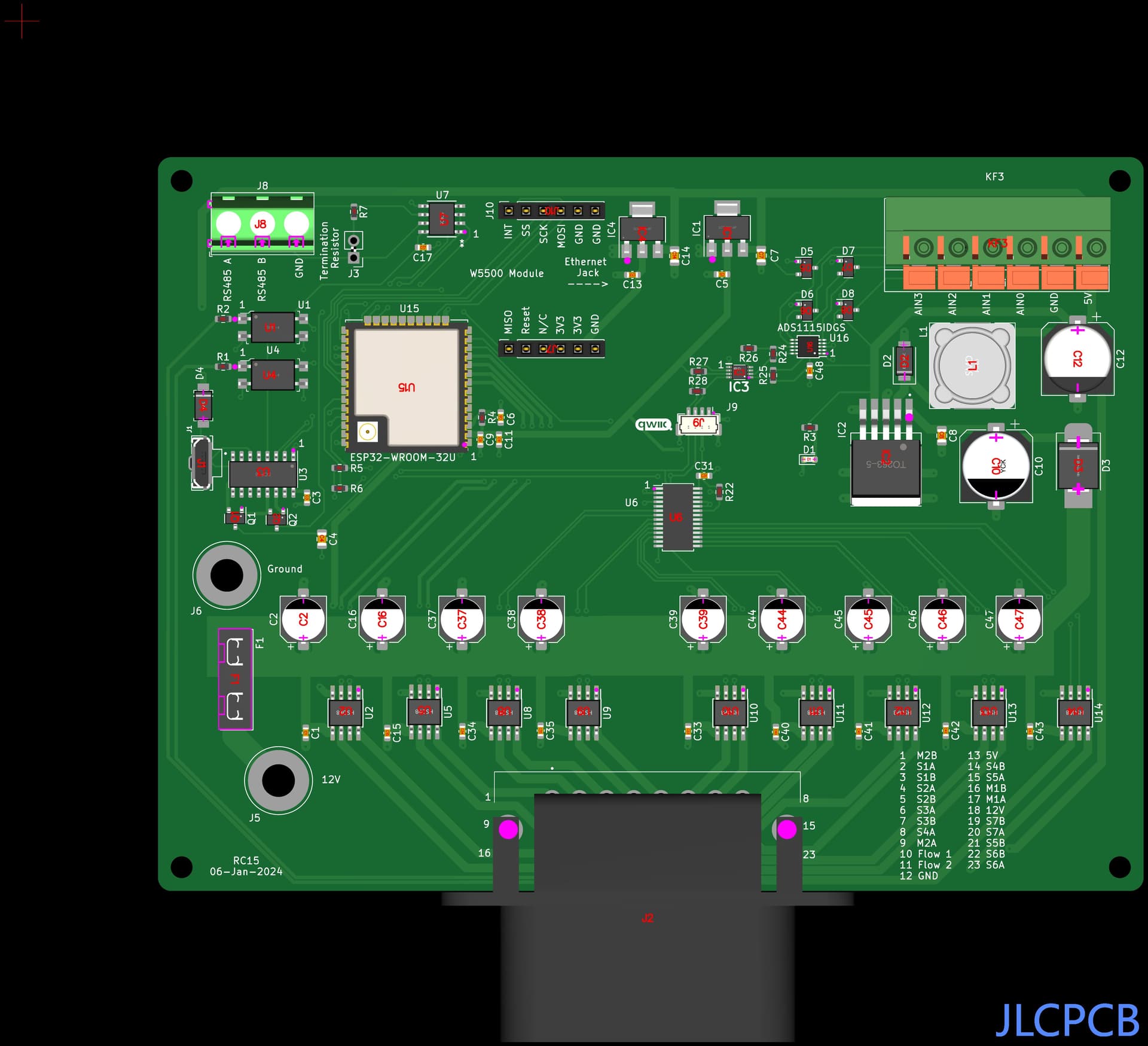

IC3 should be turned 180 degrees so the white dot aligns with the 1. J1 will only fit one way. The rest look ok. JLC will also check.
Would it be possible to build the switchbox with ESP32 and connect via WiFI ? It would be very handy to be able to activate sections individually while at rear of machine to check for blockages etc. Using RC15 rate and is working great Thankyou for the exccellent work
I’m just learning and need your guidance.
130 pp meter, 3.6 kmh = 1 m/sec = 130hz or gpsSpeed * 130/3.6 or gpsSpeed * 36.1111
Is it the number of pulses per meter?
speedPulse = gpsSpeed * 36.1111; How to understand this sentence
RC15 has a hotspot you can connect to with your phone. There are on-screen switches for the sections there. The page is 192.168.200.1
1 Like
Hi all!
I’ve been driving with AOG for almost a year now—big thanks to everyone in this community for making AOG what it is today!
I’m still pretty new to this rate control stuff and was wondering: is it already possible to control linear actuators based on a signal and groundspeed, like @SK21 mentioned a while ago?
The rate controller should be able to operate a linear actuator. On a sprayer, when used in “standard valve” mode it controls a motor to increase or decrease flow by moving it in small incremental steps, it reverses polarity to open or close the valve. That it the type of control you would need for a linear actuator.
The hard part about setting that up would be sending flow data back to the rate controller. On a sprayer the flow meter is sending a pulse back every time the turbine make a half revolution (at least the style I use) it determines flow rate by counting the pulses and determining how many pulses occur with in a set amount of time to determine flow rate. The rate controller then makes a decision on adjusting the control valve (or in your case control linear actuator) base on the flow reading.
I am not familiar with the seeder you are using, but finding a way to send a feed back to the rate controller to tell it what the seed flow is would probably be the tricky part of the project, unless there is an easy solution I am not aware of.
1 Like
I plan on doing something similar , with a short travel linear actulator(adjust door opening 25mm) , to achieve
P 2 rates , high and low. Sense the shaft speed (this will be constant ground drive),and set the target rate above and below . So the actuator will travel to its limit in each zone. Thoughts?

That should work. You might want to add limit switches (or make sure your linear actuator has internal limit switches) if the feed back from the shaft speed is constant and you set the target above and below, the rate controller is going to send power to the actuator continuously because it never reaches the target. If the actuator is constantly in a stall, it will probably burn out the motor in short time.
Yes i have one with built in limit switch
Thanks for your answer so far! Actually, it’s a fertilizer spreader with two actuators, one on each side. The actuators have built-in limit switches, so there’s no problem if the motors try to move beyond their limits.
My next question is about the rate. I don’t have one – it’s just a constant RPM via the PTO. Originally, each actuator sent one pulse per millimeter of movement (open/close), depending on polarity, to track position. That’s probably too complex for me to implement in code.
So I was thinking about adding linear potentiometers in parallel with the actuators. They can return a 0–5V signal (or more, they’re ratiometric), which would give me a position reference. Now the big question:
Is it possible for the rate control app to control the actuator positions based on the 0–5V feedback from the potentiometers? I’ve got an RC11 board on my desk, but I’m not quite sure if that setup would work.
I’d really appreciate any thoughts on this!
It might be possible to control the actuator position based on 0-5v reading and a cal #. With a sprayer flowmeter the pulses and the cal # give units per minute. If the same could be calculated with voltage it should be able to be controlled the same.
2 Likes
SK21 designed this rate controller, so his thoughts are worth much more than mine.
My skill level is still very basic. When I was experimenting with a stepper motor and his rate controller, I would sometimes use an Arduino Nano as a signal converter. I wrote code with Chat GPT as I am not skilled enough to make my own code from scratch.
You could us a code like the code below. I asked Chat GPT to write a code to read an analog input voltage on pin A1, the code then reads the 0-5 V voltage range and translates it into a variable frequency pulse output on pin D3. The 0-5V input will be output as a range of 0-40 pulses per second at a 20 percent duty cycle. This would emulate a flow meter’s output for the rate controller to use. This would be another option to make it work, although with a little more hardware.
// Define the pin for analog input and PWM output
const int analogPin = A1; // Analog input pin (A1)
const int pwmPin = 3; // PWM output pin (D3)
// Define the frequency range (in pulses per second)
const int minPulses = 0; // Minimum pulse frequency (0 pulses per second)
const int maxPulses = 40; // Maximum pulse frequency (40 pulses per second)
void setup() {
// Set the PWM output pin as an output
pinMode(pwmPin, OUTPUT);
}
void loop() {
// Read the analog input value (0 to 1023)
int analogValue = analogRead(analogPin);
// Map the analog value (0-1023) to the range of pulse frequencies (0-40)
int pulseFrequency = map(analogValue, 0, 1023, minPulses, maxPulses);
// Calculate the period of the pulse in microseconds
// 1000000 microseconds = 1 second
int period = 1000000 / pulseFrequency;
// 20% duty cycle means the pulse is high for 20% of the period
int highTime = period * 0.2; // 20% duty cycle
int lowTime = period - highTime; // Remaining time for low state
// Generate the PWM signal with the calculated period and duty cycle
digitalWrite(pwmPin, HIGH);
delayMicroseconds(highTime); // High for 20% of the period
digitalWrite(pwmPin, LOW);
delayMicroseconds(lowTime); // Low for the remaining 80% of the period
}
I’m trying to order RC11-2 and it seems C5 with part number C5162354 doesn’t exist at JLCPCB if I’m seeing it correctly.
j11 is through hole correct? (No inventory)
An alternate capacitor: RVT330UF50V167RV085 | KNSCHA | Aluminum Electrolytic Capacitors - SMD | JLCPCB
J10 and J11 are connection points for ground wires or cables. J8 and J9 are for 12V.