whoops, J1 is what I meant. The teensy ethernet header
That’s great! Thanks for your help. I’m looking forward to getting this setup!
Hi, I am trying to upload the firmware to an rc15 board,
However I keep getting this error message.
D:\projecten\AOG Rate control\AOG_RC-master\Modules\ESP32 Rate\RC_ESP32\Begin.ino: In function ‘void DoSetup()’:
D:\projecten\AOG Rate control\AOG_RC-master\Modules\ESP32 Rate\RC_ESP32\Begin.ino:128:17: error: ‘ledcSetup’ was not declared in this scope; did you mean ‘DoSetup’?
128 | ledcSetup(i * 2, 500, 8);
| ^~~~~~~~~
| DoSetup
D:\projecten\AOG Rate control\AOG_RC-master\Modules\ESP32 Rate\RC_ESP32\Begin.ino:129:17: error: ‘ledcAttachPin’ was not declared in this scope; did you mean ‘ledcAttach’?
129 | ledcAttachPin(Sensor[i].IN1, i * 2);
| ^~~~~~~~~~~~~
| ledcAttach
exit status 1
Compilation error: ‘ledcSetup’ was not declared in this scope; did you mean ‘DoSetup’?
What am I doing wrong. I double checked the libarys I am using. and updated my arduino software.
Oke Now I managed to flash it with GitHub - SK21/PCBsetup: Setup software for AgOpengGPs rate control and steering modules.
However now the serial connection keeps on resetting. Sometimes I manage to connect for a few seconds and then it resets again.
No smoke. And nothing seems to be getting hot.
After using the wifi rc option in the flashing tool I got it to stop disconnecting. But In the serial logs I keep getting this error.
rst:0x10 (RTCWDT_RTC_RESET),boot:0x13 (SPI_FAST_FLASH_BOOT)
invalid header: 0x72656874
invalid header: 0x72656874
invalid header: 0x72656874
invalid header: 0x72656874
invalid header: 0x72656874
invalid header: 0x72656874
invalid header: 0x72656874
ets Jul 29 2019 12:21:46
rst:0x10 (RTCWDT_RTC_RESET),boot:0x13 (SPI_FAST_FLASH_BOOT)
invalid header: 0x72656874
invalid header: 0x72656874
invalid header: 0x72656874
invalid header: 0x72656874
invalid header: 0x72656874
invalid header: 0x72656874
invalid header: 0x72656874
ets Jul 29 2019 12:21:46
rst:0x10 (RTCWDT_RTC_RESET),boot:0x13 (SPI_FAST_FLASH_BOOT)
invalid header: 0x72656874
invalid header: 0x72656874
invalid header: 0x72656874
invalid header: 0x72656874
invalid header: 0x72656874
ESP32 Rate is for RC15.
I keep getting this error

When I connect over wifi I can go to the webpage. En if i change things in modules i can see it restarting. I also managed to get it connected to the local internet.
But I cant seem to get any life out of my board. (also tried another board)
I am currently trying with a build of april 8the

has anybody ever had a problem with a popping condensator and step down mEZD71202A on the RC 12 board? I use mine to control a sprayer with five sections (motor valves) and some relays for controlling working lights and an electric motor that is for slope compensation of the sprayer boom.
The condensator is the one connecting the 12V to the step down (C4). All other electronics like the Arduino stay intact, just no 5V because of the blown step down
Hello All.
I’m playing with my RC15 board and running into a couple issues that maybe I could get some help with?
Issue 1 - my section valves are of the reversing polarity DC motor type. I cannot find the right setting for this type of section valve. I cannot find a “paired” option for the PCA9685. The 2 wire and 3 wire valve options do not make a difference. I tried going back a few months and running an older RC app and no difference. I cannot get any life out of the “MxA” Terminals. MxB terminals work as expected.
Issue 2 - I should be able to enable “Use Wifi Client” with my home network credentials and connect to my home network - yes? I cannot get the board to do anything besides make it’s own RateModule_MAC AP. It would really help me troubleshoot this on the bench if I can google things while the board is connected to the rate app. What am I missing?
Thank you for any ideas.
For the first issue, the valve option should be set to 2 wire. The sections are controlled as in the following diagram:
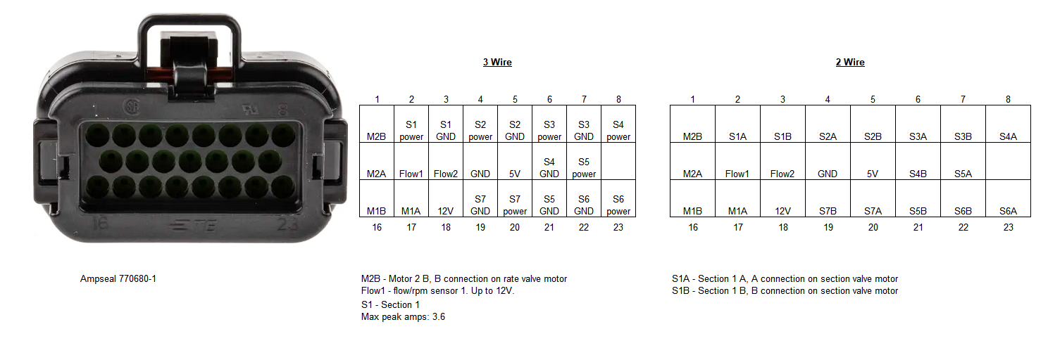
The first section is controlled with pin 2 and pin 3. One will have 12v and the other ground in one switch position and the opposite in the other switch position. M1A and M1B control the flow valve to vary the rate.
For the second issue, “Use Wifi Client” will only work if the module is already connected. If your pc is connected over the module hotspot then this will work. The wifi connection can also be changed on the module web page at 192.168.200.1


Thank you for the reply SK21. Knowing how it’s supposed to work helped, because it’s not working that way.
My problems seem to be arduino IDE compilation or library version related. While I could get the module to connect and do some things, and the module web page at 192.168.200.1 was available, I could not get the module to connect to a different network or use the paired PCA mode.
My first solution was to upload your compiled binary through the OTA page. After that all seems to work.
What I found out while typing this post is that in Arduino IDE the board should be set as “DOIT ESP32 DEVKIT V1” It’s right there in your code comments ![]()
It should not be “ESP32-WROOM-DA Module” just because it has WROOM in it. It should not be “ESP32 Dev Module” as some google results hint for the ESP32-WROOM-32UE-N4. My fault completely for not reading the code comments.
Safest thing to do is to upload your compiled binary directly.
A progress picture. I took the RC15 design and changed the layout to suit a Hardi Navigator sprayer. It should hopefully drop right in with no sprayer wiring modifications required.


5 Likes
This topic was automatically closed 60 minutes after the last reply. New replies are no longer allowed.
For me the right choice.
I just took a look at the new Rate Map feature. It looks like I have to manually edit all management zones for their specific rate. In my opinion it would make sense to set a base rate, a 100% rate just as without variable rate, and variate from there, so every management zone in the map has a fixed percentage from the base rate. So I set a base rate of 200kg, in one zone the map says 125% so the rate is 250kg. Changing only the base rate to 100kg the rate in the same zone would be 125kg, without editing the map at all.
In my case I want to use Rate Map for seeding, but I dont know the rate I have to seed at yet and would have to edit that when I get the seeds. With percentage I could finish the maps now and just edit the base rate later. Hope its clear what I mean
1 Like
I can look at the idea. Maybe have an option for both.
Hello. I am studying the topic of flow control. As I understand it, the speed of movement is taken from the AOG. But is there an option for the speed of movement to be from a separate sensor installed on the sprayer wheel.
1 Like
Hey, I am having a RC15 board and 3 wire valves.
When connecting wires to the 23 pin ampseal. Shall i then have it like this?
Section 1 => S1A
Section 2 => S1B
Section 3 => S2A
Section 4 => S2B
Section 5 => S3A
or
Section 1 => S1A
Section 2 => S2A
Section 3 => S3A
Section 4 => S4A
Section 5 => S5A