I’m looking to implement the variable rate add on to a tyne drill. (Although I just want electric drive, not actually variable rate across a given field as such)
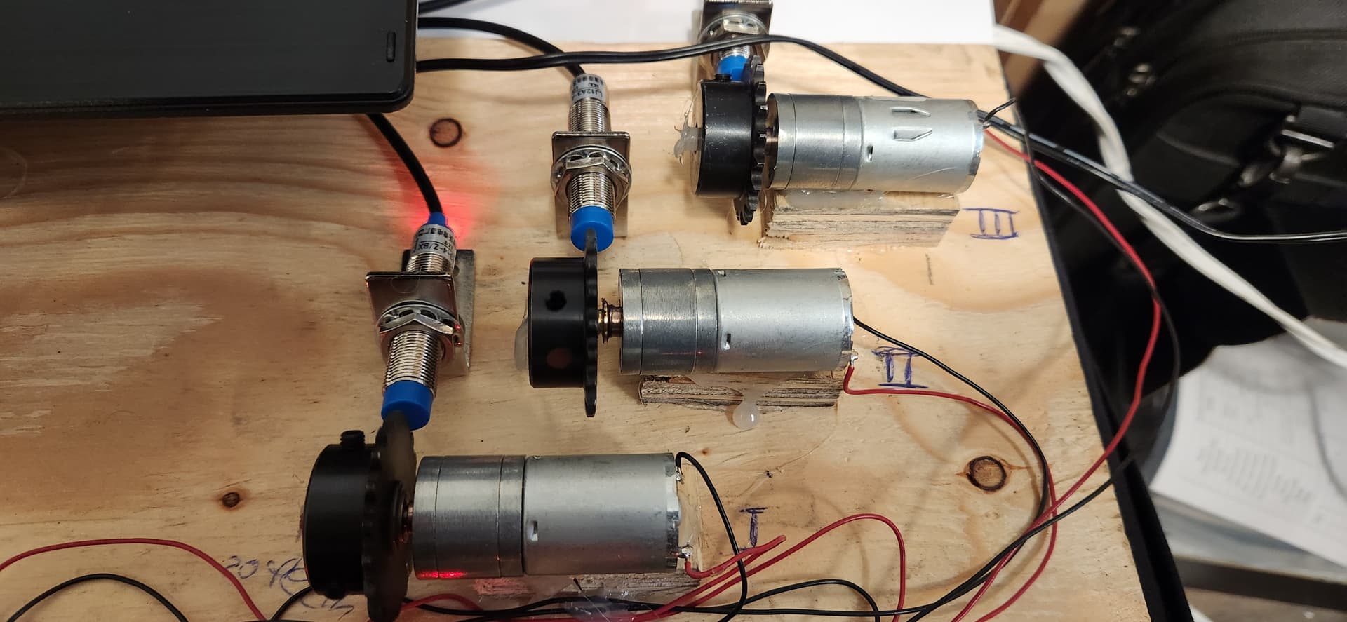
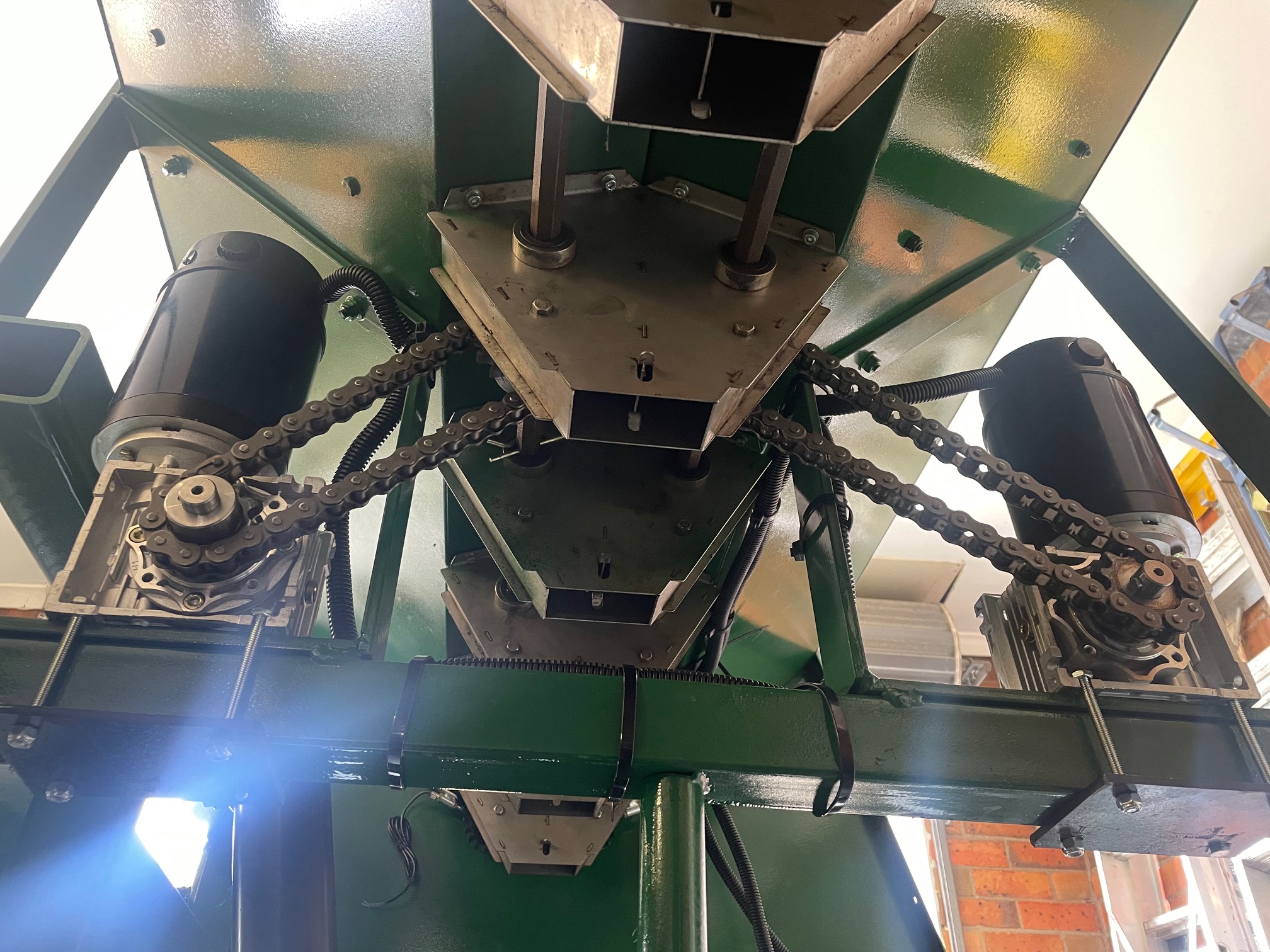
I Have 12 volt electric motors connected via chain drive to the seed and fertilizer shaft on my box.
I’m sure I’ll have many more, but my first question is What would be a suitable motor controller run each motor?
Current draw seems to be less than 10 amps when metering fertilizer.
I assume the motor controller will receive a 0-10v signal from the PCB, and this will be calculated based on some calibration and then corrected based on actual shaft feedback signal (rotary encoder or similar?)
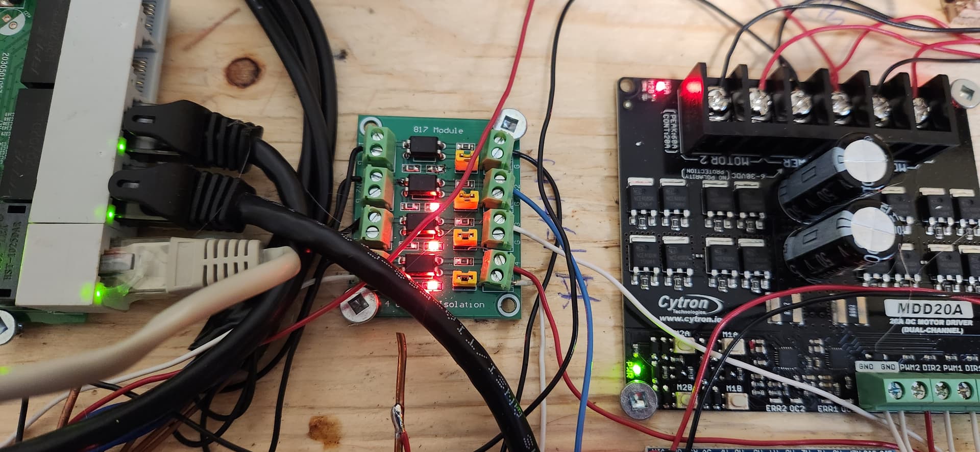
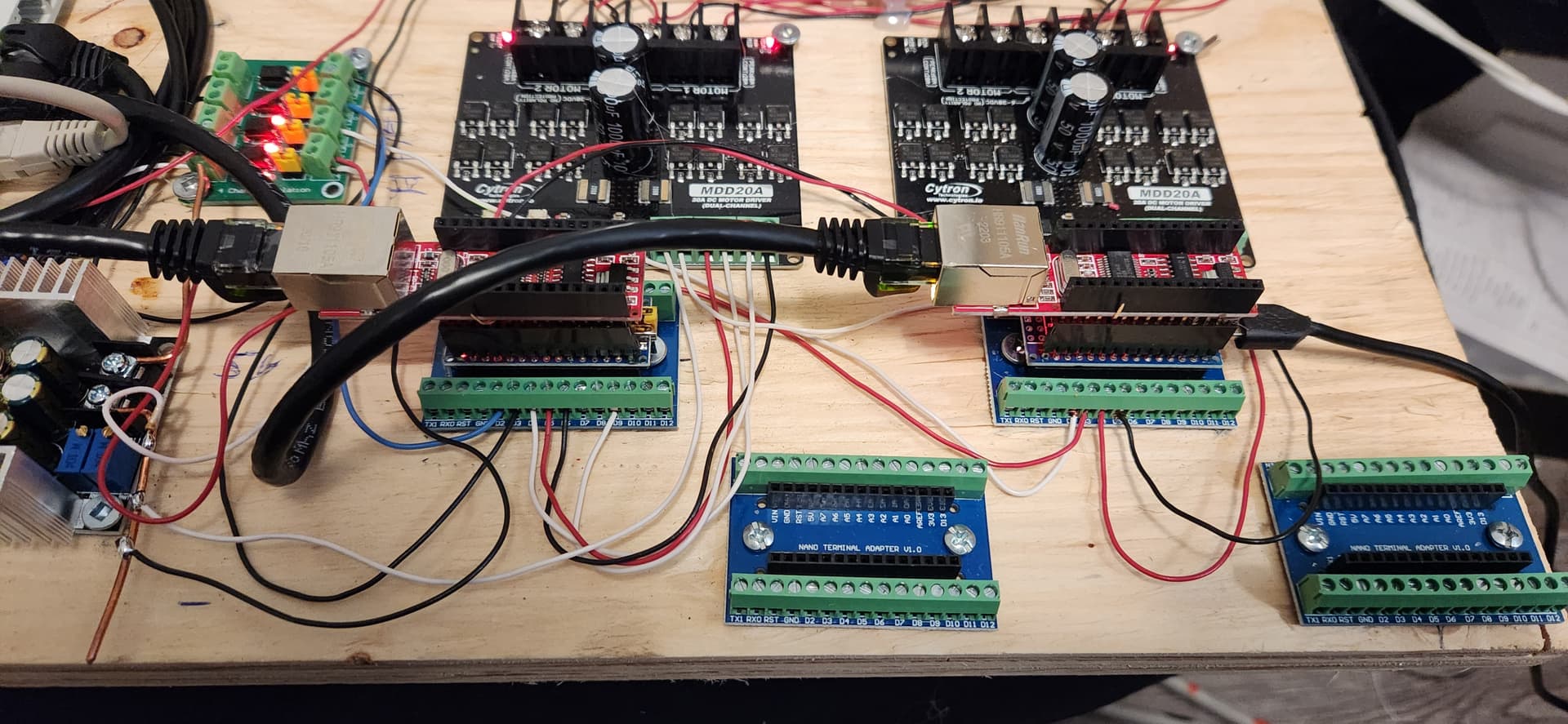
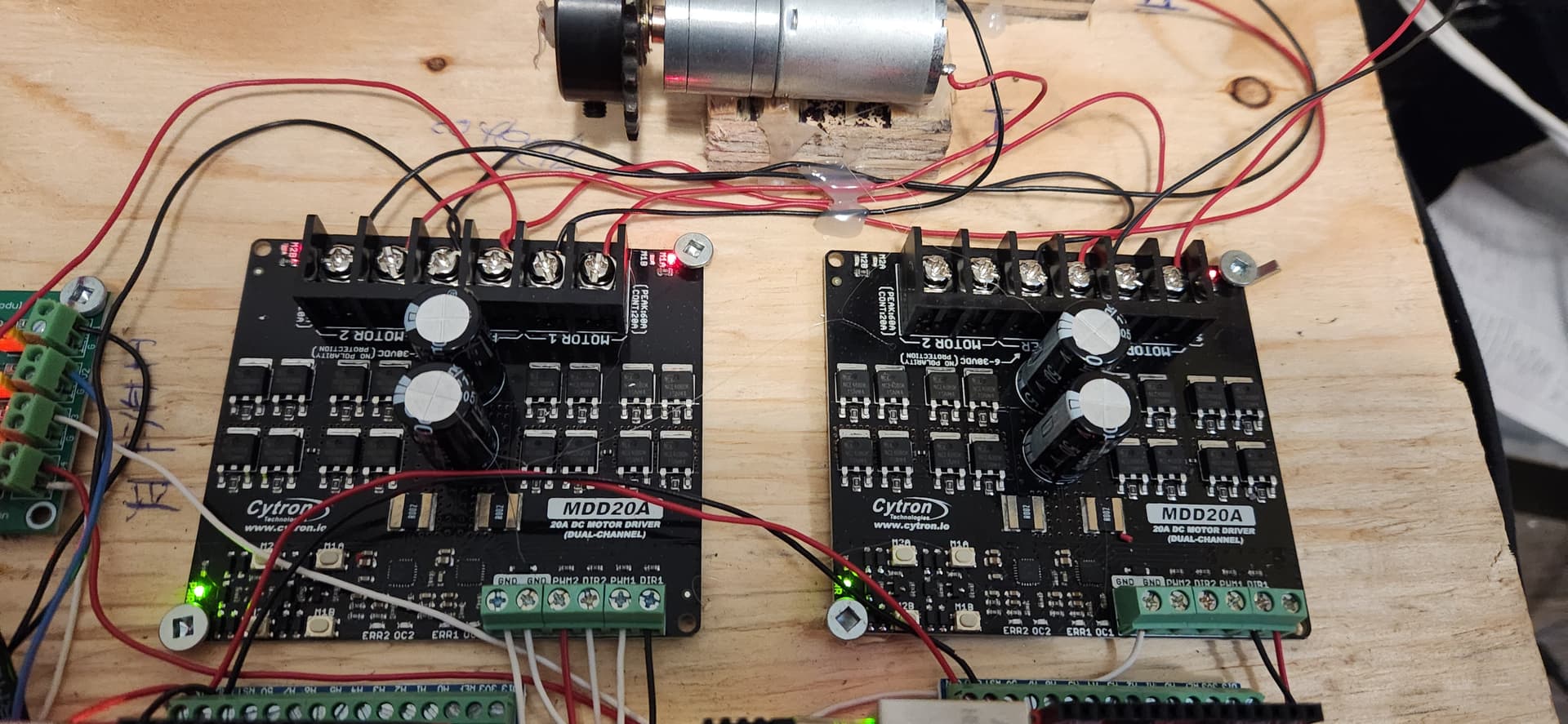
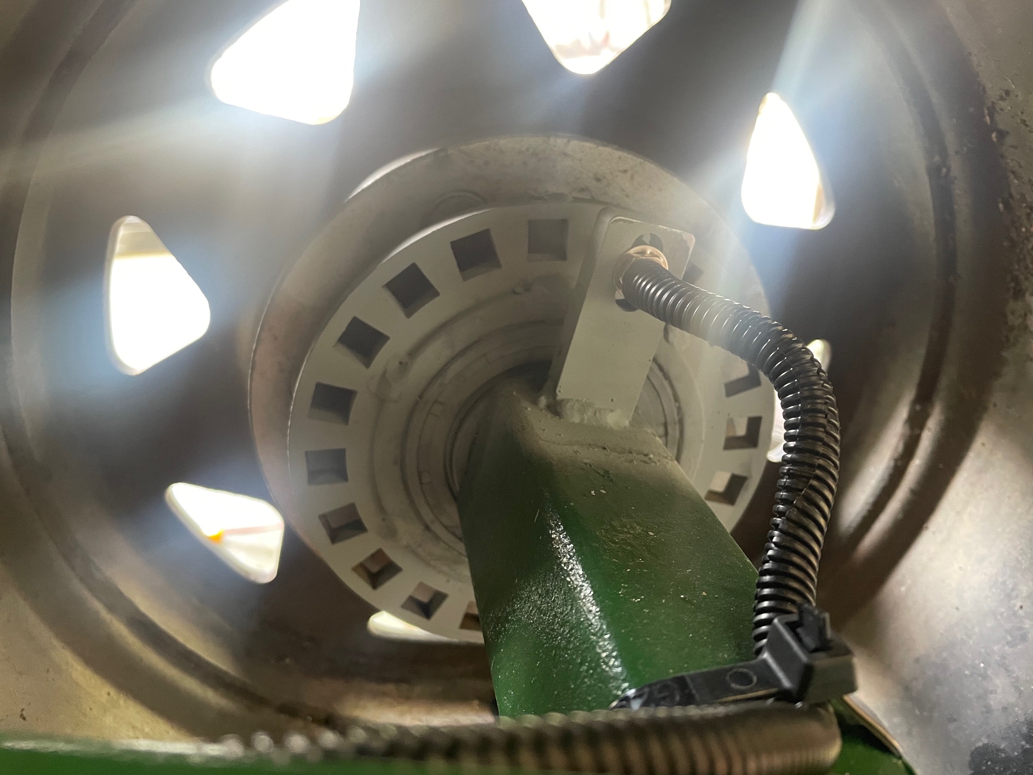
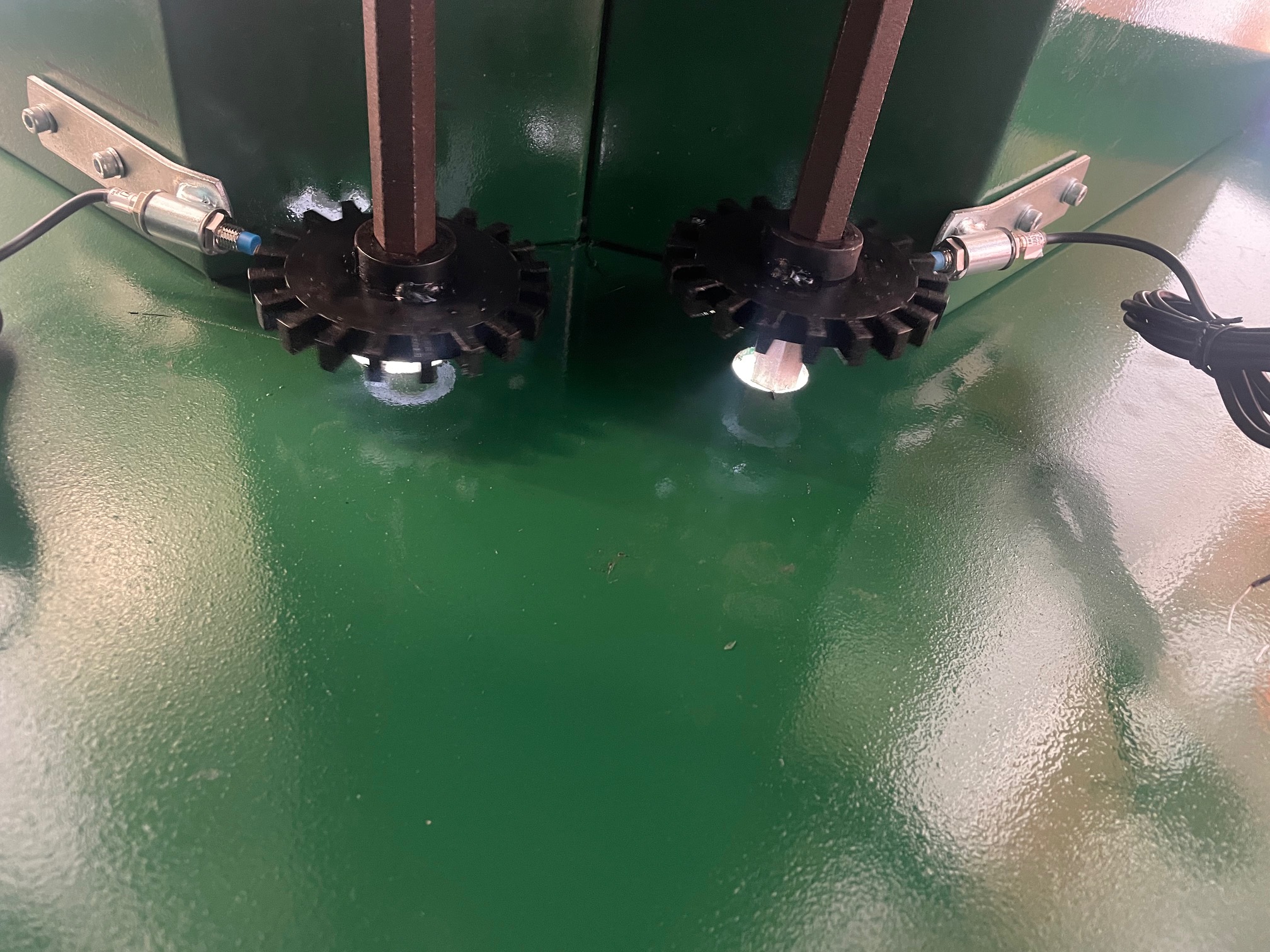
SK21s boards are desiged to take the MD13S, wich is rated for 13A. The shaft speed is picked up with a proximity senor. There are different boards in the rate controller folder on SK21s git hub. Calibration is a bit buggy, but other than that it works pretty good. I build a test with 3 motors and fan speed sensor. Each rduino can manage two motor drivers.
Thanks for the reply and photos, clears things up a little. I also dug a little deeper into the GitHub and found some info that I’d missed first time around.
Looking at your Hall effect sensor for shaft speed, how do you find it for accuracy. At slow ground speeds my fert shaft will only be doing 2-3rpm meaning the pulses might not be frequent enough for Hall effect. I was looking at a rotary encoder with 600 pulses per rev.
My max expected shaft speed is 16rpm so using the above encoder should give me 160hz shaft speed feedback, sound ok?
That should work, i used npn sensors. Not sure how the encoder deals with dirt. It might be a bit Overkill though. 160hz means a pulse every 6.25ms. In the app there is a setting for impulses over an under 5ms. You could just use a sproket with more teeth to get the resolution up. And if the sensor fails you don’t have to take the shaft apart. It works good with slow speeds as well. 52ms is no problem for my test setup. There are probably limitations but im not sure what the min. frequncy is.
I want to put a manual together to discribe setup and assembly. But that will have to wait till November and after.
On a Cameleon seeding mashine, they made a disc, to mount on the carrying wheel for speed sensing . Wheel is 1,2 m diameter, disc is put at wheel hub, disc is around 40 cm in dameter. Cuts are 3 cm deep, spaced approximate 5 or 7 mm. Sensor pick up from side of disc. G1031.pdf (135.4 KB)
Just found this amazing item on AliExpress. Check it out! C$1.61 23%OFF | LJ12A3-4-Z/BX LJ12A3-4-Z LJ12A3 Inductive Proximity Switch Three wire NPN normally open
That’s what i used.
Or these will work as well.
Just found this amazing item on AliExpress. Check it out! C$1.42 | Cloweit SN04/SN05/PS-05/PL-05/TL-Q5M/TL-W5/GKB-M0524 5mm Metal Detection Limit Switch 6-36v Inductive Proximity Sensor Switch
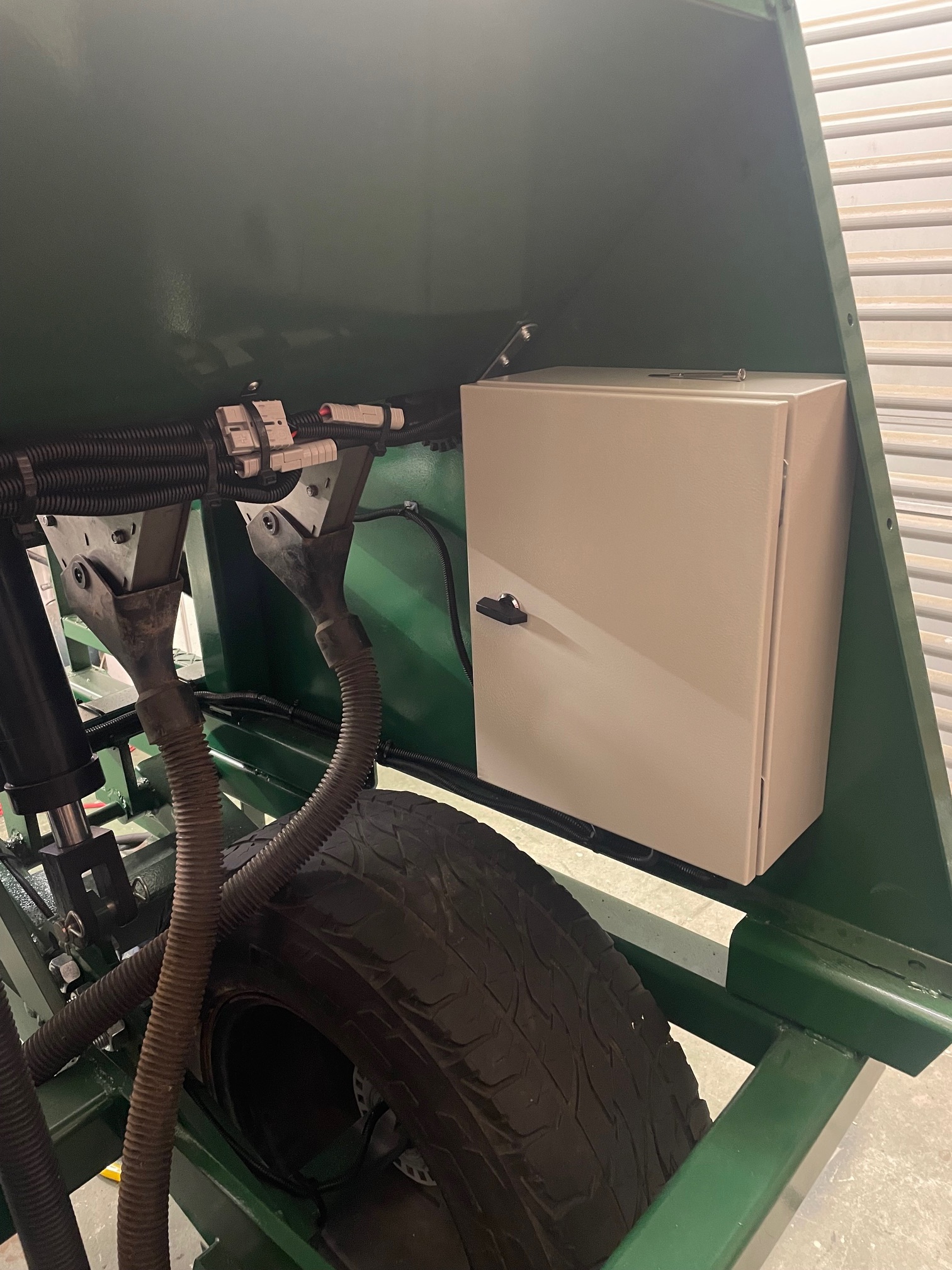
Bit of an update on this project for anyone who might be interested.
Machine is built and motors are fitted. It’s been tested in the workshop but not yet in the field.
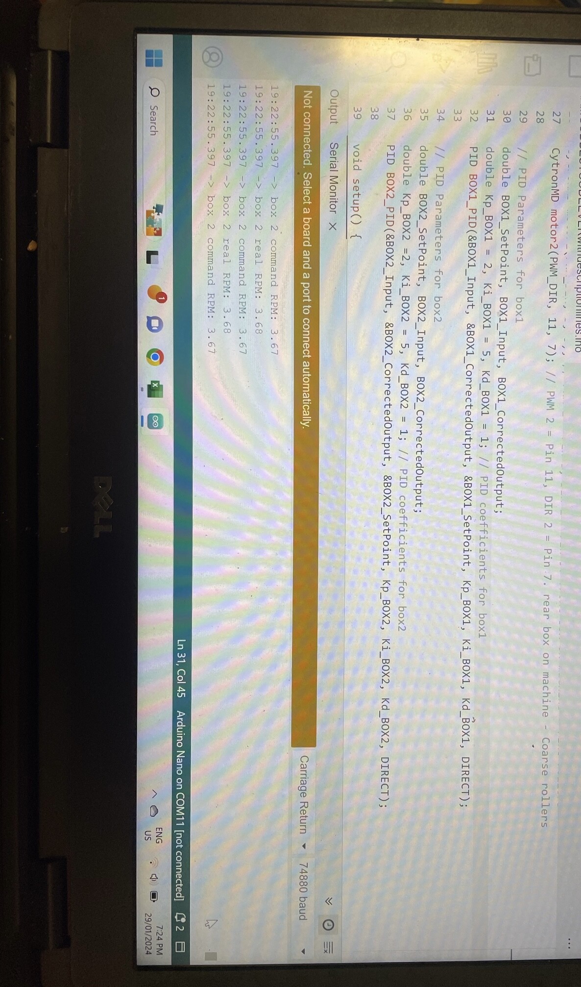
I’ve written the code myself in IDE, with some help from AI websites and at the moment I’m just monitoring shafts by printing data to serial and using serial monitor in AGIO, which is running on my toughpad anyhow as I use it for spraying.
There’s no interface between AOG and this machine. It’s simply a stand alone electric drive drill running off a nano.
I’ve left all the variables which are specific to my drill at the top of the code so it’s easy to modify for another similar machine. This is also where the rate is entered and where calibration data is entered.
Long term a friend is hoping to put an Android app based GUI together for calibration and for entering seed rates.
Machine variables will hopefully be in the app too.
I have Included a PID loop for each motor but found to hard to tune so currently running the automatic mode and default settings. It still seems to work quite well.
This machine will be set up for 3 products/motors. Ground speed is from a wheel sensor as I wasn’t confident getting it across from GPS.
So would this same idea work for variable rate fertilizer say on a john deere 1750 ground driven planter? Just hook the motor to the driver shaft for the fertilizer?
Would the electric motor be strong enough? I have a 6 row strip tiller that id like to put dry fert boxes on. Just get the fert setup off of a jd 7000-1750 with the sprockets and hook this motor up, and away you go. But that fertilizer mechanism turns fairly hard, not sure if the motor would hold.
Put a torque wrench on the shaft and find out.
I’m using 250w 1400rpm motor with 100:1 reduction box, I’ve then got another 1.5:1 reduction in the chain and sprocket.
Serious amount of torque and really over kill for the job. It’s about this wattage where the motors go from hobby to industrial quality though so that’s why I chose it.
Using 20 amp cytrons but the motors are usually drawing less than 5 amps each.