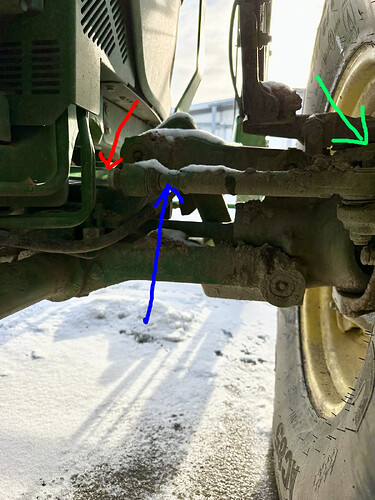
sure before posting i look at whole thread, I also looked for tips in other topics and places. To be honest i didnt find many examples installations on this type of suspension but mayby i didnt see or understand something. Could you be more specific?
I could find many instalation (linear or rotary) to part that i marked with red arrow but i cant do that - this parts rotates around which distorts the rotary readings and will damage the linear one. It would be perfect to use the part marked in blue because as it is already behind the joint and no rotation on it, but on every bump this part moves up/down and in other directions, which also affects the sensor.
In the examples I found major modifications to use the location marked green (from what I know, the original sensor is located there if there is one - in mine there is no space for it so I would have to make a lot of modifications ), and from what I can see it is a very large modification requiring a lot of skills and equipment which is beyond my scope.
I hope that maybe someone has another, simpler solution…
