Work or Steer switch?
But it is not important in both cases…
You need a (Inductive) Proximity Sensor NPN NO (Normal Open)
Like this 10-30VDC Inductive Proximity Sensor NPN NO
When the sensor encounters metal
appears on the (Black) output wire, - or GND or 0V
- Brown = VCC
- Black = Output
- Blue = GND
It might be Monday before I get it but for sure will report back.
Brian, if I pull-up\down WORK switch, will the Tool paint the passed space during AOG driving? I want to put a switch on the rear hitch, and make Tool to paint the field when the hitch is down. If its not already in the code, can you give a point, where to put the code into Aog? If I understand correct, it should be a Section Button press event.
My tractor has electric lifting arms.
I found 5V logic on the tre mode switch.
The functions are Up, Hold and Down.
So I connected Work Switch wire to the Down functions grounding pin.
Down = mapping (painting)
Hold = No paint
Up = No paint
The code is already in Arduino.ino. So no programming required.
You can also use a proximity sensor.
LJ12A3-4-Z / BX or equivalent NPN Normally open
Which pin on the IMP switch from the PCB do you connect to tractor’s grounding pin? The “0” or the “Com”?
I’m trying to get my slurry tanker to paint in AOG. I have a Toggle switch like this 
on the slurry tanker. Do you think I could do the same with this switch? Connect the grounding pin to work (IMP) switch on the PCB?
Middle pin to ground.
I’ve used one of these as a work switch. Easy to mount and quite forgiving. The actuating rod is a spring so bends to take up excess movement.

It is pin marked “0” if you are going to use tractor 's grounding pin.
Separate Switch must connect between “0” and "COM.
1 Like
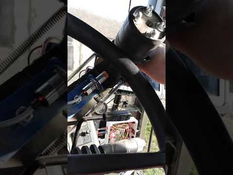
I finally got the new sensor. It’s a NPN NO - LJ12A3-4-Z/BX. I called this the work switch but it’s on the Steering motor assembly.
I get 12 volt on GND - VCC and the black signal wire when it is NOT in proximity to steel. When close to steel the data wire is in the range of 52 MV. Is this acting the correct way?
I still can’t get # to change in AOG.
I don’t understand what the problem is
Brown = 12v
Black = Output
Blue = GND or -
ropecope, That’s the switch!! In AOG it will not switch when motor is in work position. Brian says in this vid
no sense doing anything else if the switch isn’t working. I’m measuring voltage at the junction of wires from PCB and switch.
Hope this makes sense ??
Did you solder a wire where R8 (resistor 8) is on the pcbv2?
So on the 3 pins beside each other you must have 12 v between +v and gnd/com
Between O and gnd/com there could be a little less than 12 v, because it passes through a resistor and the led inside optocoupler.
Edited: changed vcc to +v and added com after gnd
I must have skipped school the day that R8 was discussed! So take the resistor out and jump the 2 holes with a wire? Just got done using tractor so I’ll be able to work on it tomorrow .
Correct, no resistor only wire 
Larsvest, I don’t know how you could know I had a resistor in the R8 position but changed it to a jumper wire and works great.
THANKS
I’m 


Glad it works  . Your measurement sent me in that direction.


