That is for the ByNav, which I doubt you’re using, so don’t worry about that.
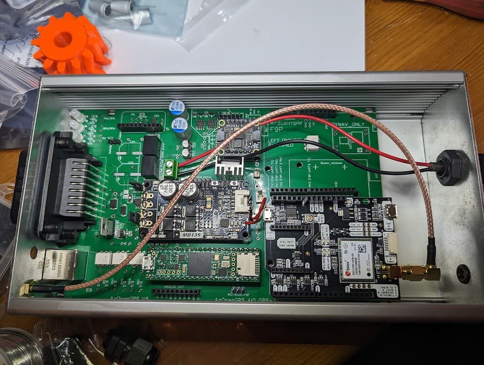
Too late for the headers, the boards are already here, but I now understand why people say that. Even as a complete newbie I am removing several of the ones where they used multiple pieces for one header as they really don’t line up at all. The MP1584EN is for the bynav which is an alternative gps board correct?
I’ve read several comments, most of which appear to be older saying that the BNO085 or CMPS14 should not ideally be placed on the main board due to interference or accuracy issues. Is this still a problem or has it been addressed where it is now okay?
The cmps14 is out. (Magnetic sensor can’t be stopped, and not as fast as bno)
Bno085 is setup so it doesn’t use the magnetic sensor, so not really sensitive to electrical interference from blowers and other high ampere users.
I have my bno in same box as autosteer (teensy type with panda) placed at flor level in tractor.
Oh and yes bynav is an alternative to other GPS receivers.
1 Like
This is the one I went with. https://m.aliexpress.us/item/2255801127848863.html?spm=a2g0n.order_detail.order_detail_item.4.315ef19c9HInZz&gatewayAdapt=glo2usa&_randl_shipto=US
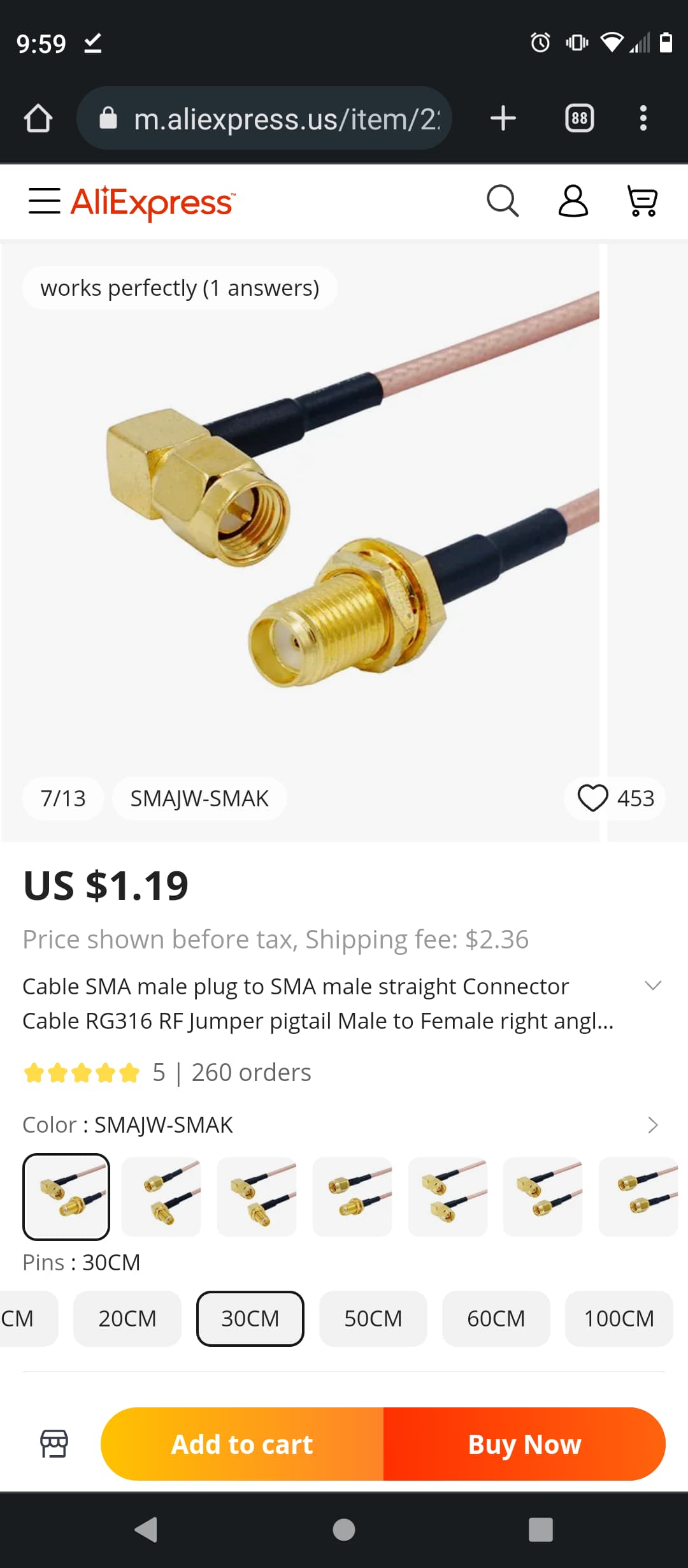
Cable Assembly Coaxial SMA to SMA RG-174 7.874" (200.00mm) at digikey
One thing I have used with previous commercial gps displays and would really like with this system is what I call a work switch. Generally I would use a simple spring limit switch mounted somewhere on the implement and when the switch was connected it would paint my map on the display. Is this an option with this and if so can somebody point me in the right direction or walk me through how it works.
AMP_Connector.pdf (193.2 KB)
Pin 9 on the ampseal should do it.
Yes pin 9, connect to GND to close the circuit, can be active low or active hi, selectable in AgOpenGPS
Thanks guys, I was looking at that exact picture and couldn’t figure it out.
Is the remote/pressure jumper used at all with a steering motor or is that just for hydraulic steering systems?
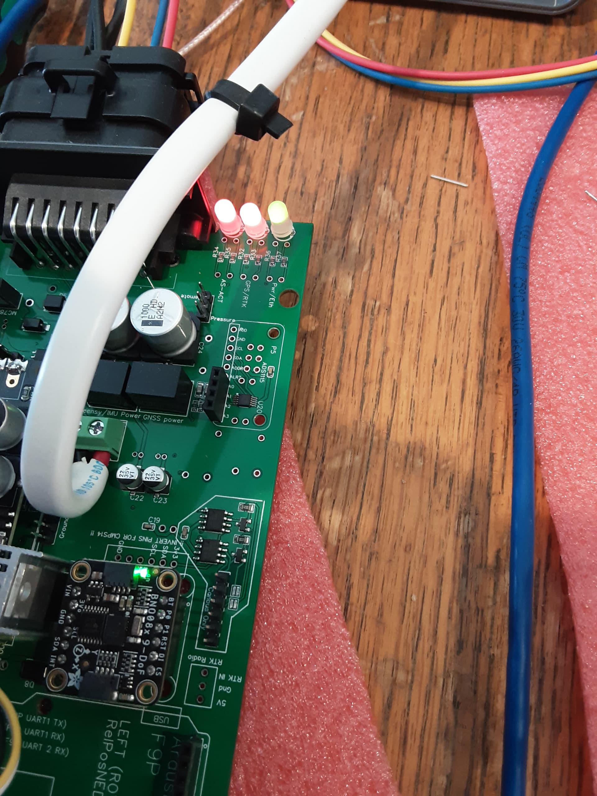
So when I power my board through the ampseal connector, 12v to pin 22 and ground to 23, I have 5v at the gps and on the 5v pin to the teensy, but that is all. There is 5v coming out of both of these voltage regulators.
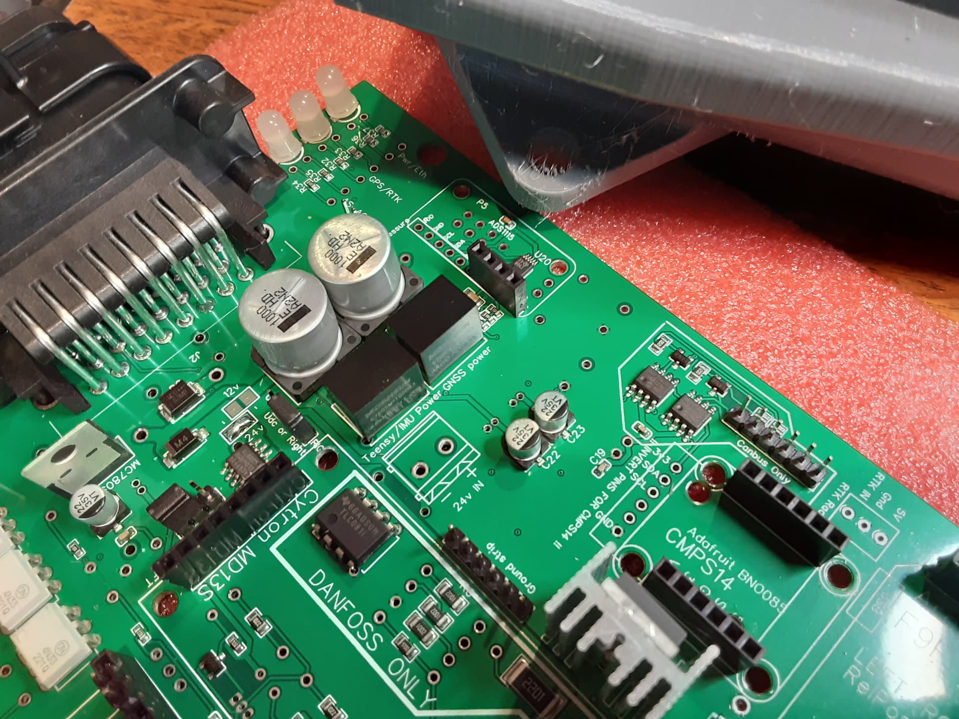
No power to pwm1, pwm2 reads 1.4v which seems totally wrong, and there is no 3.3v anywhere. What am I missing now? What is the voltage path from those regulators to make 3.3v for the teensy and imu? What could I have possibly broke for the cytron to get no or irregular power?
Teensy is supplied by 5V, IMU is supplied by teensy’s 3v3 Output pin ! There is no 3,3V Power supply necessary for Standard PCB!
Micro PCB uses 3,3 V Power supply to support the both F9P Micro’s.
Awesome, I was somewhat panicked. What about the cytron? Is it some way only powered when steering is on? And my low voltage on pwm2 is just the freewheel mod in action?
Input power to Cytron should be constant I think. Outputs will only show when steering or when MA/MB buttons pressed (unless you’ve performed any mods to it)
What is input power to the cytron? 3.3v, 5v, or 1.5v like I seem to have? The 12 or 24v selected by the solder bridge just passes through the cytron to the motor correct? Or does it also run it?
What do you mean by that? Why would you need to wait for a group to buy micro? Is it more expensive?
Yes, In a group buy you can have the micro+antenna around the same price than the simpleRTK2B+antenna kit.
You can buy micro anytime but they will be a little more expensive.
1 Like