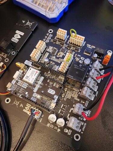
Does anyone know, how i can read the Output of ACS712 on the A2 Pin of the ADS1115 on which the steering sensor is also connected?
I’m using a PCB of Andreas Ortner and his new PCBs don’t have a A0 to the Arduino where you can connect the ACS712 to disengage Autosteer when you turn the steering wheel by hand. So my plan is to read out the ACS712 through the ADS1115 because it has A2 and A3 left.
Can someone please help me
There was a dialog last month which may be interesting for you:
Case IH Puma 230, autosteer ready - Projects / Success stories - AgOpenGPS
You can do as fivefinnishfarmers did You only need the upper part of schematic!
You find it around the middle of post 1.
https://onedrive.live.com/?authkey=!AHnhw6mFnSn6gS4&cid=A23BBF94342BFE2A&id=A23BBF94342BFE2A!2077&parId=A23BBF94342BFE2A!2055&o=OneUp
Thread here:Case IH Puma 230, autosteer ready
Would it be possible to direct connect to A0 directly on the nano? The trace on the V2 is just the same as a wire.
Carefully iron and slip the nano A0 pin above the board and hook on with a DuPont wire, or just solder a wire on top of the A0 pin.
A bit more difficult because ortner PCB do not have standard nano. I can’t see on pictures if there even are any other " nano pins" taken out to edge of PCB

I see now it just has the chip integrated into the board, little tougher to modify.