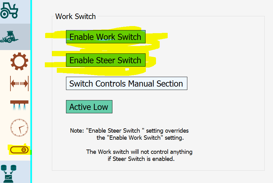
It appears as if you aren’t using the newest version so try setting button in that menu. But don’t forget to Send plus Save. Otherwise the Arduino doesn’t get updated. Because i think in this Version the general function from Switch and Button is inverted, so try using the other option.
It seems that end of this topic is mostly about @DCol ‘s project. Maybe it’s wise to move the discussion regarding his project to a separate thread to in-progress section, isn’t it?
Can @Vili or some other admin do that please?
Here are the posts containing questions and answers to his project:
57, 59, 60, 76-100
Just trying to keep the forum clean and easy to read ![]()
Good idea, I was feeling bad for hijacking your success story with my so far no success story, thanks @FiveFinnishFarmers
what is connected to A2 in the bottom off the picture
I was trying would the pressure sensor be picked up there, but it doesn’t work yet.
I have the same setup and cant get the presure sensor working
On the ON/OFF I have put an external button it turn the board on and off. On D6 and GND I have put an switch to turn steering on and off.
The problem with the pressure sensor I think is that on Andreas Ortners board there is no analog input, the connectors in the bottom for WhellAngel on A0 and the other A1, A2 and A3 are going trou the ADS1115, so we ned a new sketch for the Arduino, that can read the presure sensor
Yes exactly, I was talking to him about it last week he is working on a solution.
Hello, I have resumed the autoguiding of the puma 230 and I find that I have no current in pin number 11, neither with the tractor running nor with the rear button on. I have taken 12v power and gnd from another place to power the pcb, I have connected the 6/2 valve to 12v and the pcb seems to work correctly, but the wheels do not move. With the multimeter I have seen that no current reaches the left/right valves when I activate the cytron buttons. Driving in the field, the was goes perfectly and in autoguided the citron leds turn on when it crosses the line to send power, but it does not reach the valve. Is there a place where it cuts off the power that is sent from the citron?
I have original wiring, tractor ready for autoguided.
Have you checked that connector is in place at back side of autosteer switch.
Does any of the 3 relays (behind cover at your right knee) click when you turn the key (Without starting engine)
2 of them must be active to make connections from 716 to steer valves, off course only when autosteer switch is on.(don’t remember exactly but the 2 maybe only work when engine is running)
Also:When you have the autosteer switch out, check if there are 12 v on any of the leads in that connector (fuse could be missing, see wiring diagrams for your specific tractor model)
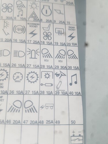
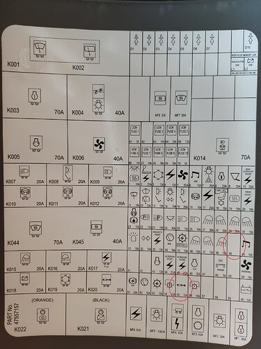
Edit about fuse: I remember something like fuse 56 was for autosteer , but the spot/hole for that fuse is empty on the NH t5 175
Has just been at the place where t5 175 is, and here fuse 39 is also for autosteer.
When engine is running, I can hear the 2 relays click when I flick the autosteer switch at right back coloum
Thanks for the instructions, my tractor has different fuses than t6, the guide seems to be 55. Until Friday I will not be in the tractor, but I have not heard the operation of the relays. I’ll check #55, there’s nothing on #39. The strange thing is that in the summer I looked at pin 11 and yes there was 12v but now there is nothing between 11 and 1.
One relay (named something like starting cut off relay) click when ignition on engine not running, and you flick autosteer switch.
With engine running (needed to have 12v on 11) the 2 other relays click when flicking autosteer switch. (Safety cut off, of connections to autosteer valves)
The other safety thing is the connections to 6/2 Valve( I think originally power would be shut off when driving over something like 20 kmh)
Fuse 55 was blown, it was changed and everything came to life. the pressure sensor works well at 1 bar, I made the Y cable for the was signal and for gnd, but I still feed from the ecu. It is in differential and reads the angle well.
The steering setup is a bit tricky, I put the one in the first post and the tractor kept lurching. Now I have put this:
Was zero: -1.79
CoG 145
ack 113
max angle steer 27
P=75
Max=86
Low=P21
Min=13
Look Heat 2.8
Look—Gain 1.5
Roll 0
integral 19
I haven’t tried stanley, only PP. He makes the turn quite well but it takes a while until he catches the line, it seems that he goes too far and then he returns to catch it. I have only tested at 4 km/h, if it goes faster it seems that it does it worse.
If anyone sees how it can be improved I would be very grateful.
I don’t have IMU as I haven’t been able to get BNO 085
To avoid the problem of not catching the line straight, it helps to make U turns that have about same radius or a little more, as the set/possible real life turn of the tractor. Keyhole form does not do U turns so well.
Gracias, lo probaré
I didn’t read the whole topic, but why didn’t you use the Canbus directly to drive the tractor?
I think nobody started messing with the NAV Controllers Canbus. Everyone just unplugged the NAV and built in their own PCB.
I asked Common Rail to make the can bus and this was the answer:
(https://discourse.agopengps.com/t/can-en-case-puma/8236):


