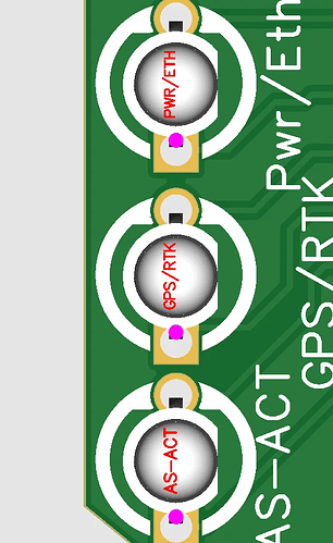
Yes this is standard,
I will try starting over see if it goes smother
I ordered standard pcbs about week ago and had no issues. Some pin headers were not available but that’s all.
Same here. I ordered some standards 10 days ago. One LED part number was out of stock. Selected an in-stock replacement and the boards are in DHL’s hands now. ![]()
I wanted to order new micros the last few weeks, but there were always a lot of parts missing.
By chance I saw that you had released 4.5 and I was glad that I hadn’t ordered 4.1.
Everything was there when I ordered. But then I got an email during production (I’ve never had that before) that C88743 is missing, the two transistors.
But better that than SMD parts ![]()
Question:
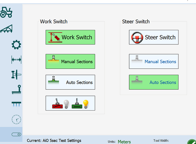
Can I connect 12+ to the steer and work switch? Are there optocouplers installed?
Both have optos, and you only need to connect to ground to activate the inputs. It’s safe to connect +12v but that won’t activate the inputs.
I ordered a PCB but due to lack of parts in stock, I replaced C459134 with C409522 and received the following message:
Since we are not so sure about the polarities of C409522 is correct or not. Could you please kindly check if the polarities and placements of the components are correct in the below picture? Is it okay to proceed with production?
What should I reply?
I believe in that orientation the pins (and colors) match, it’s just a smaller LED but they should still be able to install it. Even if they rotate it 180 degrees it’ll still work, your green/red will just be swapped.
Where can I find options for enclosers? I have been looking around the discourse, but because everything moves so fast it’s hard to keep it all straight.
either a 3D printed version or an aluminum enclosure?
Thanks
I’ll add some links in the original/top message. They’ll make their way onto the wiki yet too.
Thanks!
Yes, it works. The appliance socket outputs 12V+ and I have connected it to the workswitch.
And if there is an opto there, then nothing can happen?
Why are you connecting it to 12v?
If you want a 12v signal to turn on the work switch then use the 12v to trigger a NO relay where the work switch can then be connected to Ground.
I did that after someone told me not to connect 12v to it.
It worked, but I installed a trigger. Wanted to know if it was basically ok.
Did you end up subbing c88743? I received the same email. If so what part number did you use? Wasn’t sure if C311672 was suitable
have skipped it and place it self.
Under the Matched Parts column is it ok if some of the parts have a message saying “Multiple lines in the BOM have been matched to the same part. Please check if matching is correct.” ?
This is for the v4.5 PCB
Have any of you used the pre-order parts section on JLCPCB website so that all the parts are ready to go?
Thanks.
I have some pre ordered parts. They automatically use from your “parts inventory” if possible.
Another printable option for the case
https://www.printables.com/model/587713-enclosure-for-agopengps-pcbv41std-v3
https://www.printables.com/model/775428-enclosure-for-agopengps-pcbv4xstd-v4
There is also v4 version, good for um982 and rvc external IMU. Many faceplates to choose from, and 3 mounting ways. Internal M6 screws, external M6 screws, and panel mount M6 screws.
Hello all. I am trying to order the micro PCB from JLCPCB, but it is short the following items: C88743, C2897369, C132363, C22456. Any suggestions for alternatives? Thanks in advance!

