AgOpenGPS
All in One PCB
Hardware
del_boy
30 April 2023 15:25
1057
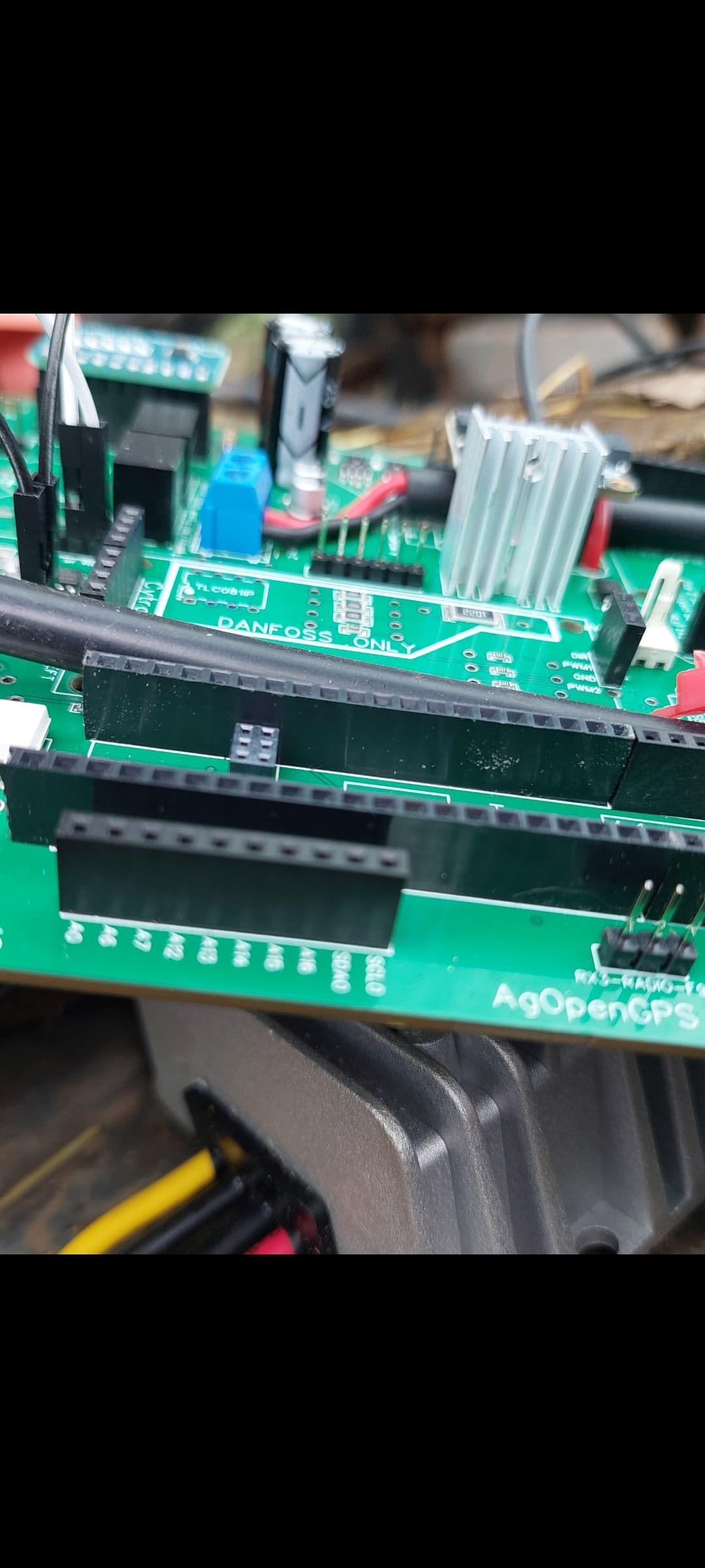
The block in the aio board is lower down so i think its good
Screenshot_20230430_162345_Gallery
1080×2400 141 KB
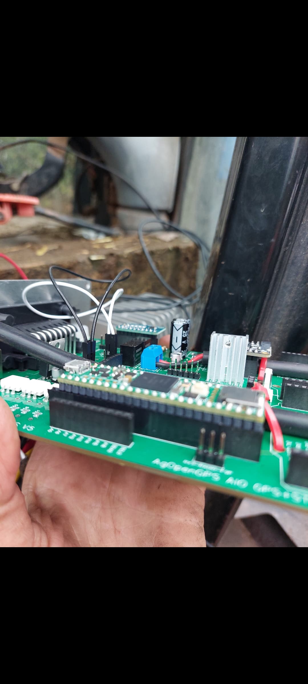
Screenshot_20230430_162354_Gallery
1080×2400 134 KB
Teensy sits down level on the header pins
show post in topic