Post some pics of you screen and button settings and all
No the lights don’t come on the cytron in simulator mode apart from green power light.
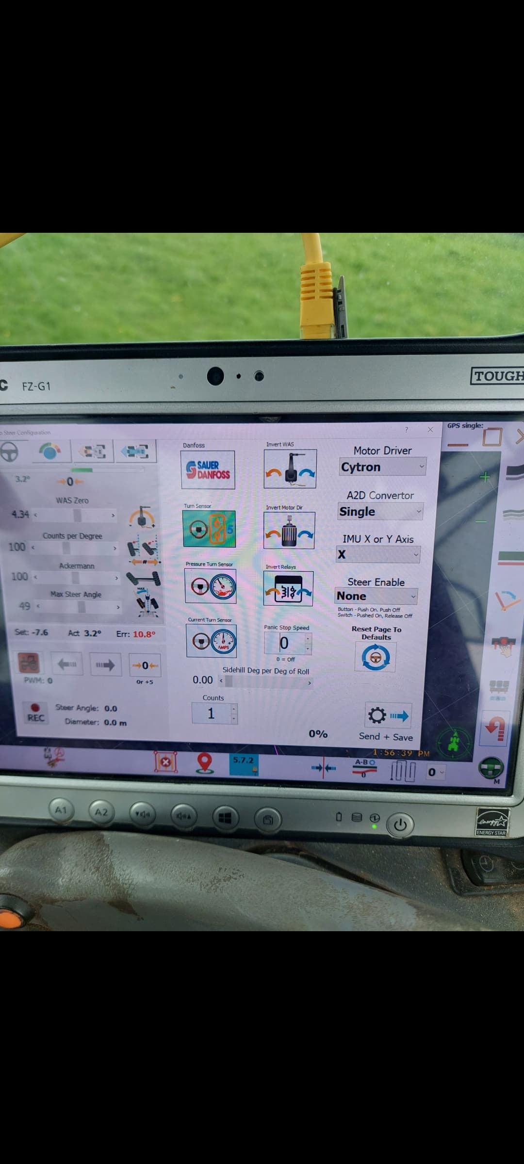
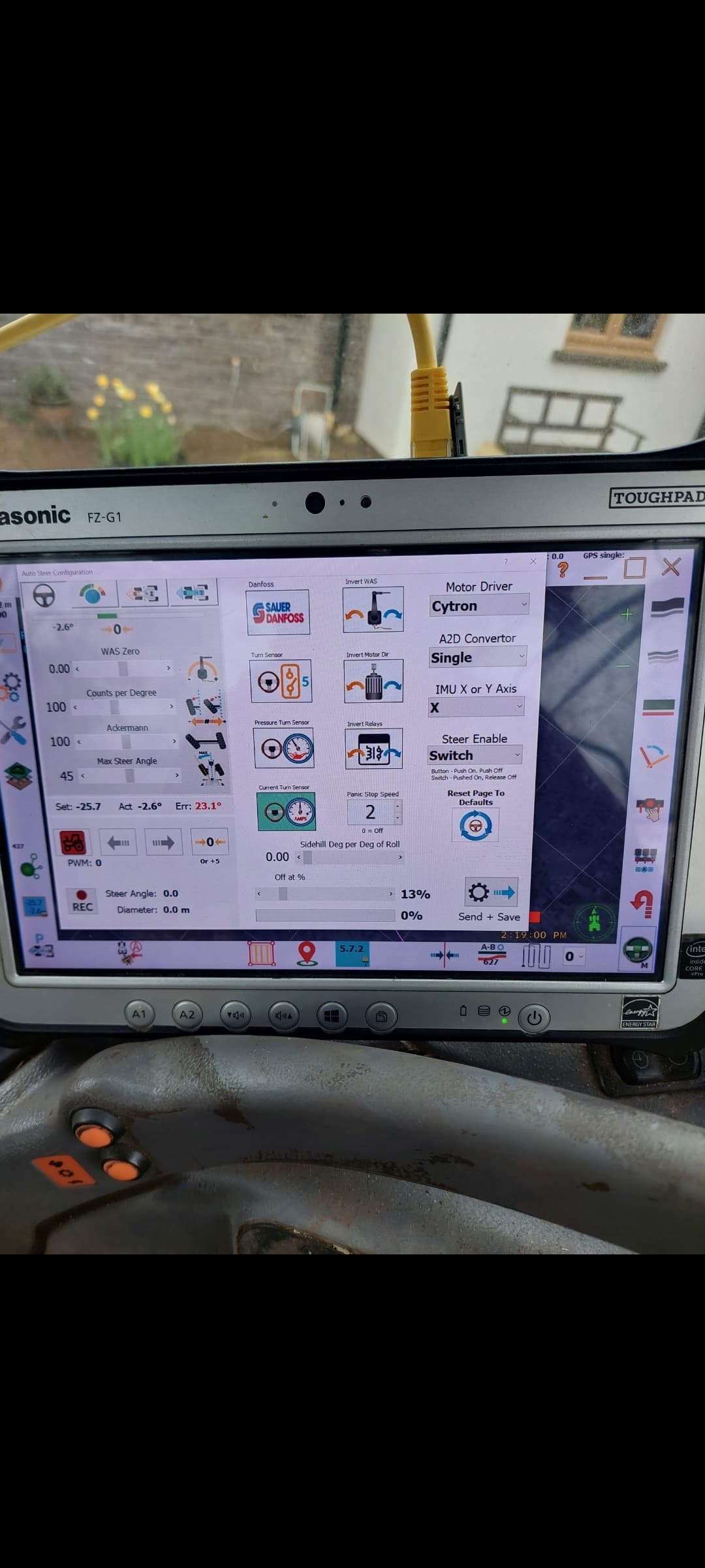
Picture of my steer settings.
Green tractor arrow pointer and green led light on the pcb for steer module
With the pcb powered up its creating force of the motor of you try turning the steering wheel.
Been throught setup wizzard but still cant get it to steer.
Tried selecting the none and switch for steer enable.
You need current sensor for steermotor.
I havnt modified the cytron, do i need anything connected to the PWM2 through hole? Will be using the relay to turn off autosteer eventually if i get it working
no as long as you dont try disengage before you use the relay.
Set panic speed to 0
raise your current sensor to 50%
Ive already tried raising the sensor current to over 50.
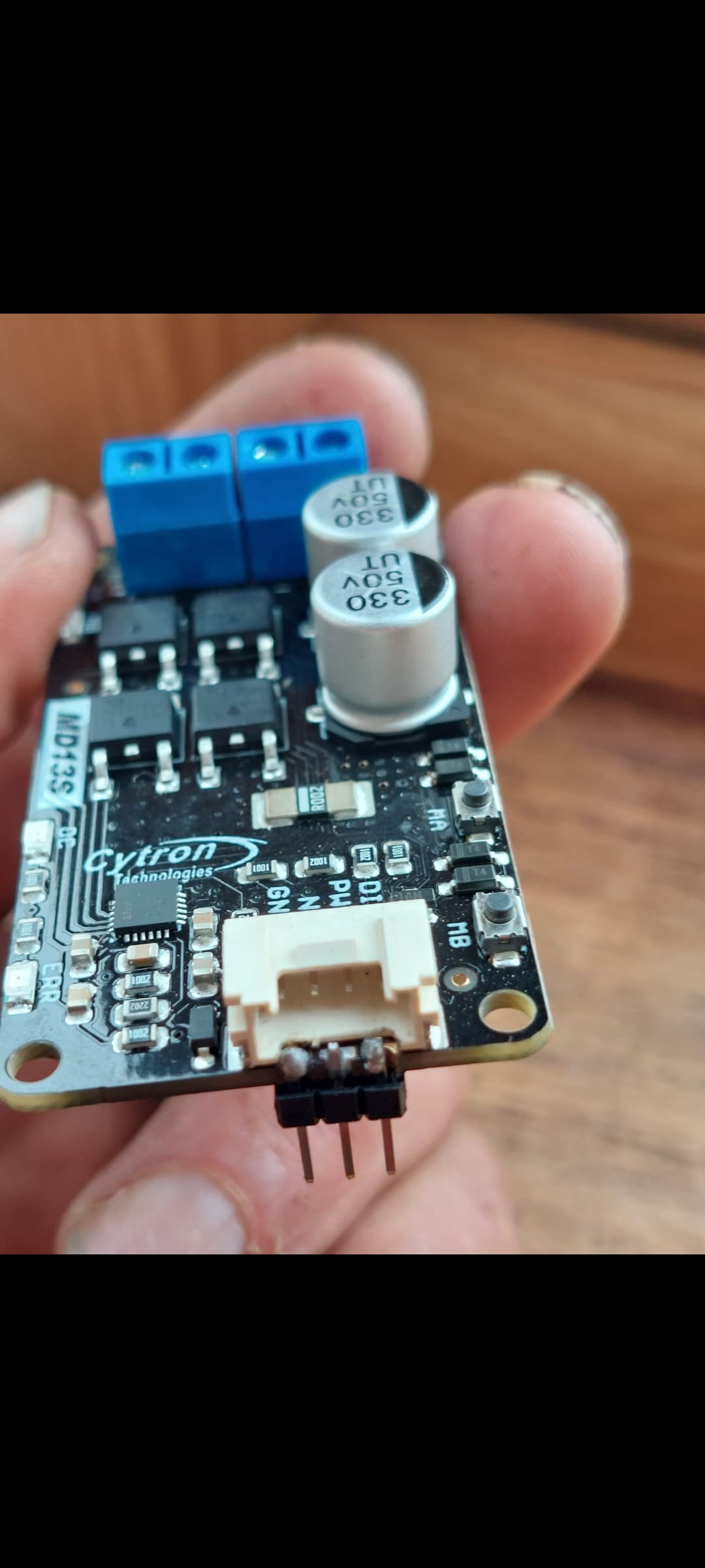
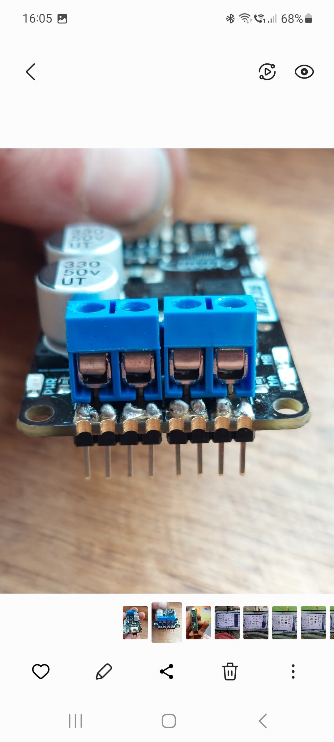
Ive voltage tested the 3 pins at the end of the cytron and nothing on any of them, should they have any power? Strange the ma and mb buttons work
MA and MB buttons will not require input from Teensy, check you haven’t got a bad solder joint on the Teensy.
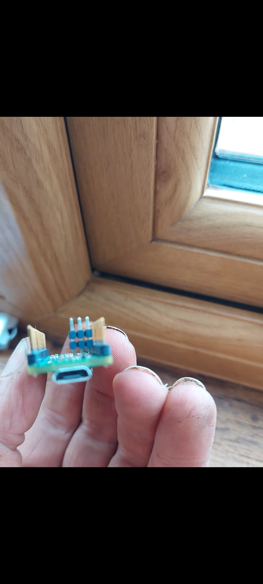
On the pins underneath the teensy? I brought the teensy 4.1 with header pins attached and they were also in the pcb aswell but i can look ![]()
Should i be getting any voltage on the 3 pins at the end of the cytron? Getting 0v on all 3 at standstill
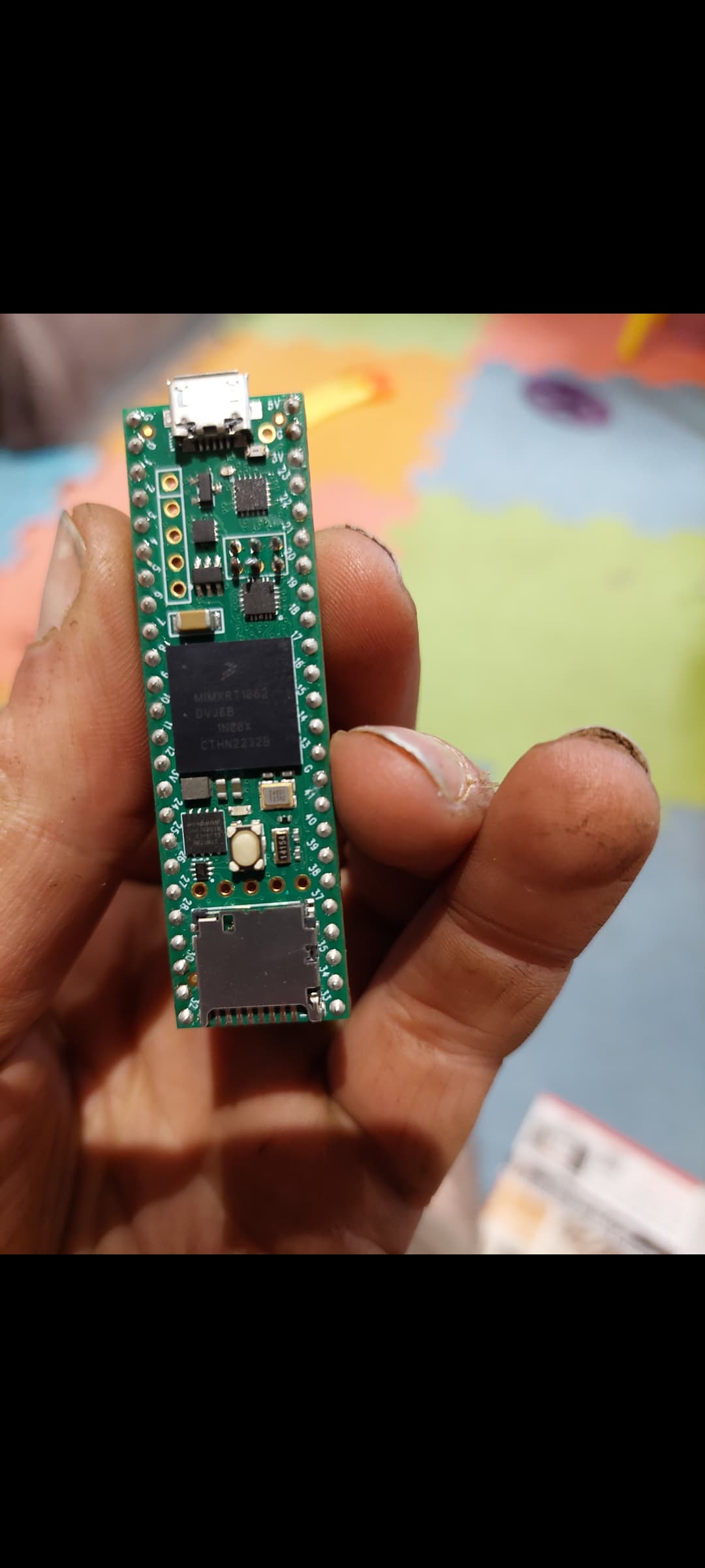
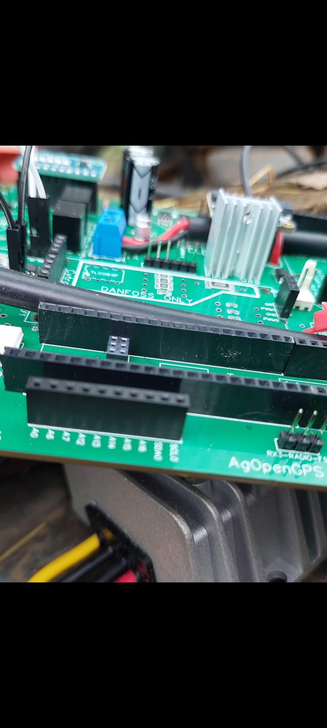
In one of your pictures one of the PCB Teensy headers is longer than the Teensy!?
The Teensy outside header pins looks good.
Cytron looks like the right hand pin isn’t soldered the best.
You could test the socket though with Teensy putting a steering signal.
The ethernet pins are longer your right. Will be causing me problems?
The teensy flashes orange light on top so its getting power and the steer module light is green on the pcb
The block in the aio board is lower down so i think its good
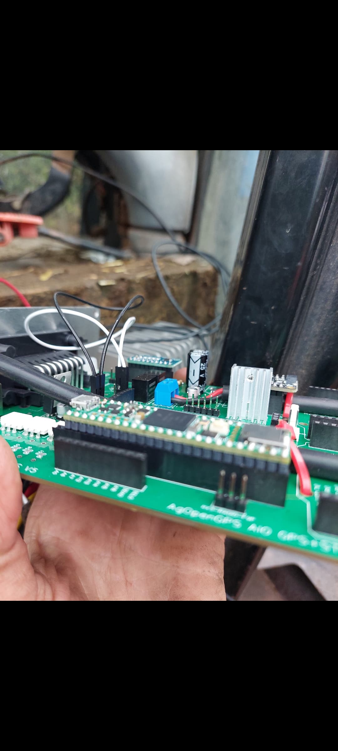
Teensy sits down level on the header pins
Solder the middle on the cytron. It looks like not connected
Longer Ethernet pins ok, they can push into the header socket below.
I meant the female header on the PCB is longer than the Teensy, should be 24 pins long each side.
Blasted some more solder on the middle pin and tried again and still no luck.
Well spotted. I had a few bad attempts at cutting them the right length as it kept splitting the last pin out, was running out of header pins so decided to make that one longer and i pulled the last pin out to avoid damaging the pin i needed to use. 10 out of 10 for spotting that ![]()
How do i get the teensy to put out a signal for me to test the pins on the cytron
If you have an f9p. Connect everything and fire up AOG in normal mode and make an ab line and engage autosteer. It should attempt to move your wheels to the proper steering angle but it won’t be able to. What is even better is if you setup a was so it has feedback like a real setup. For mine I use a small 12v gear motor and some string wrapped around its shaft like a winch that pulls on a WAS.
Will it do this in simulator mode? Should the motor spin in simulator mode as it tries to keep to the line?