I don’t understand why you want to use simulator mode to test the motor. Wouldn’t it be a lot easier to just use the drive feature in the steer setting? Make tractor green, make aog wheel green, and touch the left and right arrows and see if you have pwm above the green tractor button. And so on.
1 Like
Im not sure how i can test the pwm when the tractor has to be moving to get the green light on the pcb for steer module.
When stationery its all red.
Thought maybe in simulator mode when all the lights are green i could then test the cytron without the tractor actually moving

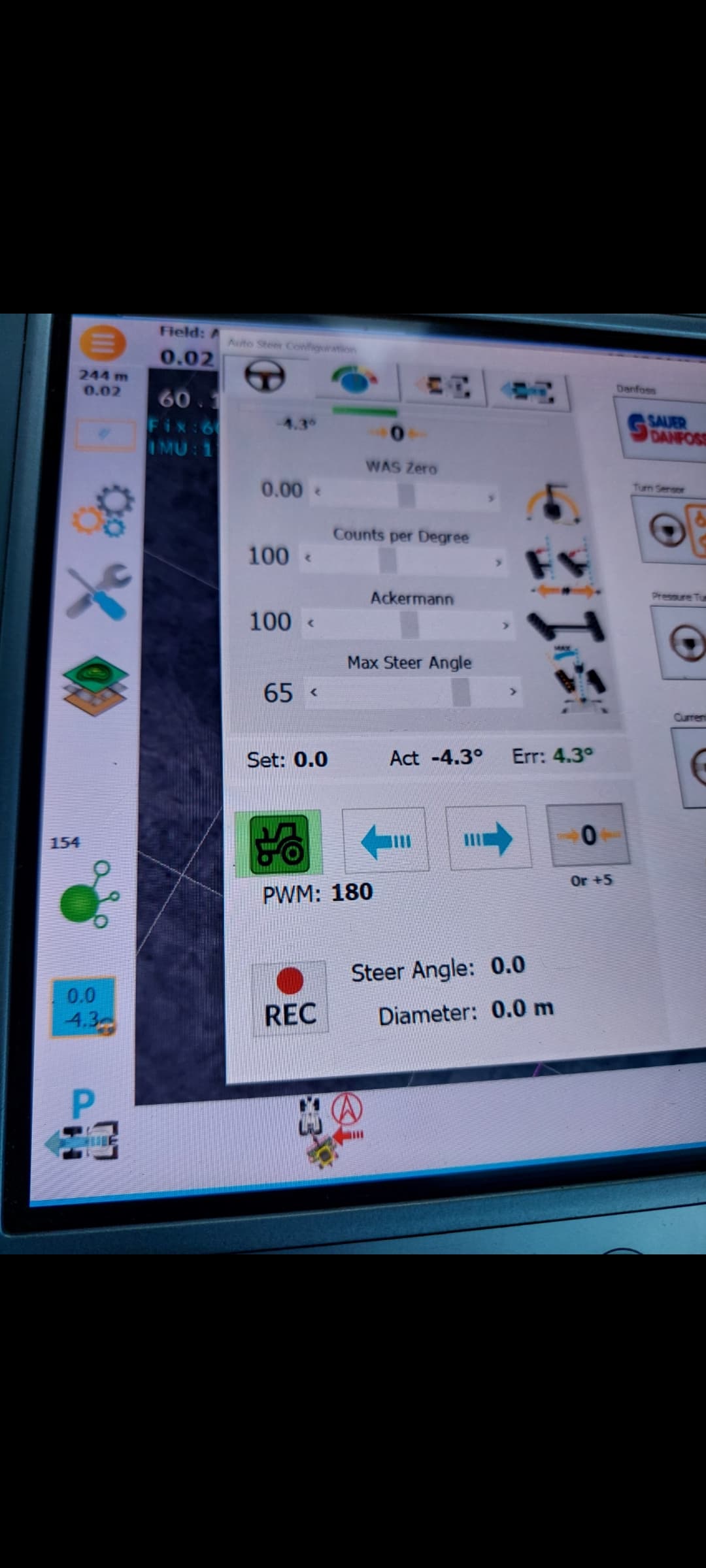
Ok i pressed the pwm tab on the screen and the light went green on the aio for steer module.
Green auto steer switch activated and tractor pointer also green.
Not getting no output on any of the pins on the rear of the cytron.
The little black 4 square tabs on the top, the front 2 are testing at 24v the rear 2 are testing at 9.4v.
Does this mean the cytron is goosed?
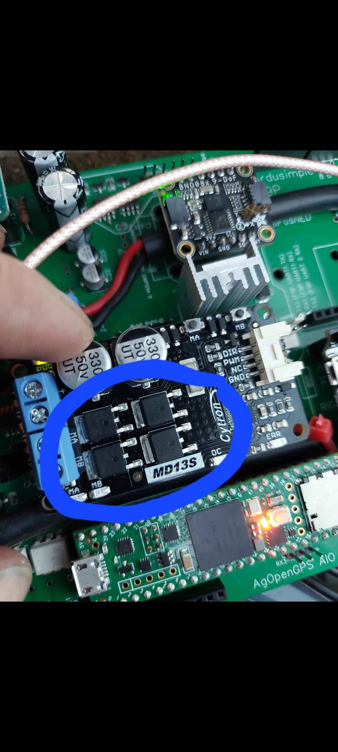
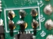
Get out the microscope and have a good look, that middle bottom one looks like a wizards hat rather than a soldered joint ![]()
To test so you know what you are looking for.
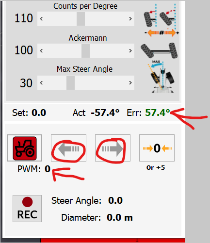
With wheels fairly centered, engage the drive feature and autosteer like you have done.
click the little arrows beside the tractor button to make the error over 5v. look at the pwm amount just under the tractor button. If you have pwm over 0 under 255 then you should have voltage at pwm1 pin on the cytron. pins are ground, pwm1, and Dir. pwm1 should have something less than 3.3v when you have pwm in the steer screen. Dir should either be 5v or about 0v I don’t recall.Power for one direction, no power for the opposite direction.
I don’t recall the direction of MA/MB, but with power at dir should select either ma or ma. When you have 0v on dir the other direction shoud be enabled. so using the arrows on the steer screen, make the error go from green to red and see if ma/mb changes on the cytron. Once those are working, you should have motor output. If not then check motor power connections.
Your right i best buy a magnifying glass ![]()
I agree with Andy. Those connections, even if they aren’t giving trouble today need fixed.
Use a sharp pointed solder tip and don’t be afraid to put some heat at the connection. When then the temperature of the pads is hot enough the solder will make a nice teepee and cover the entire pad. Then you can feel confident in your connections.
Thanks for I’ll check again. I had pwm at 180 and an ‘error’ of 4.3 for maybe not enough. I didn’t try it the opposite way either so will check again.
Looks like my soldering on the teensy ethernet pins needs some more welding aswell.
Will do all this and report back.
Many thanks ![]()
Just a quick update as i had a bit of spare time this morning so i checked all the connections across the top of the teensy both sides and the cytron both ends to the underside of the pcb and they are all making contact.
Will hopefully have some more time later to to the pwm test
Are you sure you have the program properly installed in the teensy? At least mine did not flash the light anymore after I got it installed.
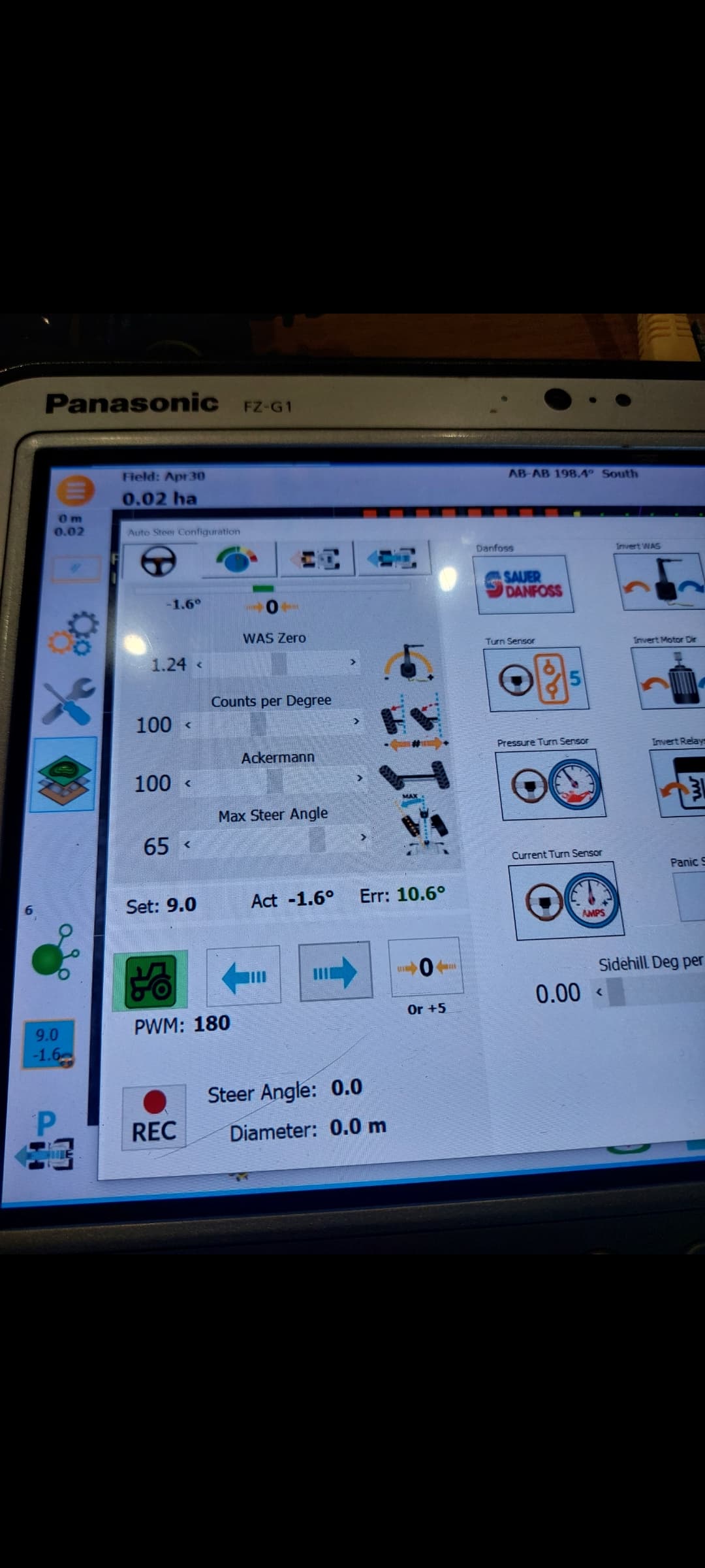
Ok so did some more testing in the pwm.
Steer module green and tractor pointer green.
With pwm on 180 error in red at 10* im getting DIR 3.2V
PWM 0V
NC 0V
Moving the steering error to green 10* im getting
DIR 3.2V
PWM 0V
NC 0V

Ive flashed the teensy twice successfully i think. Didnt have any errors come up.
The orange light on top is flashing, should it not be?
Nothing on pin DIR when in the green error but showing voltage in the red error
What does Teensy show over USB?
This is what i had when i checked as described in the wiki for the teensy 4.1 software uploading

Can i test any pins on the teensy for output when i use the pwm test function
Dir is okay.
Adc failed in your serial monitor. Cytron is disabled as a result. What does agio look like? Pic.
What does that mean?
I flashed the teensy a 2nd time when i had troubles with the was and as i thought it went ok.
Shall i flash it again or do i have a problem?


Below is a screenshot from the tutorial on the wiki and this says exactly the same as mine so i presumed mine was right ![]()

The wiki was saying that as a board wasn’t connected at the time - the Teensy was flashed standalone, not plugged in.