All in One PCB

I am running power from the bent bins directly to the cytron. I was afraid of burning my PCB because apparently power lines are thin on the first version of it. And I haven’t got definitive answer if they are capable of running Phidgets motor on 24v.

If your using the 24v motor your ok on the traces front, it was the 12v motors that drew too much power. I think @TeddyStamford put up a video of testing the amp draw on a 24v motor was was something like 3.2v draw at full turning.

Hi, I found such a picture here in the chat, do you think the wires of this length do not have a negative effect on BNO085?

Works well!

edit:
without soldering, you can use:
Flexible Qwiic Cable - Breadboard Jumper (4-pin) - PRT-17912 - SparkFun Electronics

1 Like

Thank you :+1:

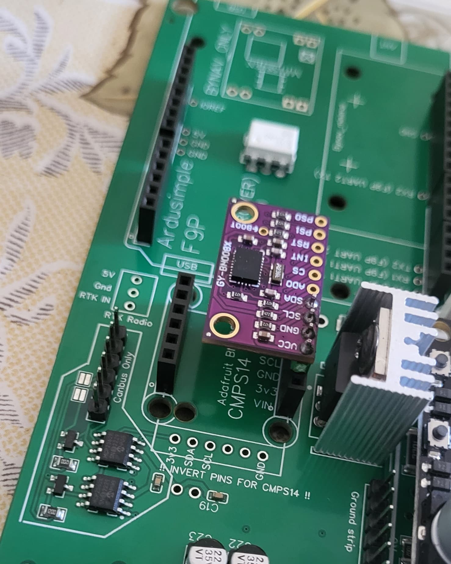
Guys, I have questions, I don’t have 3.3v for BNO here:

3.3v is near “invert pins for cmps” writing, is that expected?

I want to try bno from aliexpress, but no voltage there:

3,3v is output from bno.
Depending the board, Vin is already 3,3v. Check with a multimeter

3.3 volt for bno comes from the teensy.

Its plugged in board… as Pat said Vin pin has 3.3v but 3v3 pin don’t and it shouldn’t okay… so I have to use wires for this IMU

Another question, its my first board… :stuck_out_tongue_closed_eyes:

I can use USB to Ethernet adapter and connect board to tablet no need for extra USB for f9p?

Correct. No extra cables needed.

1 Like

Do I need to make any changes to .ino for connecting this way?

I uploaded TeensyModules>V2.5>Firmware>Autosteer_gps_teensy_v2_5>Autosteer.ino

No changes as far as I know

1 Like

Anyone select 2oz copper option for outer and inner layers? I know it costs more but will there be fab issues if traces are too close with a 2oz board?

Looks like 13 parts are not available when I uploaded the standard ampseal board. I might just order parts from DigiKey and build it all by hand. Soldering SMT parts isn’t an issue for me. Have boom microscope, Metcal iron, and a hot air pencil.

I followed Ethernet setup on GitHub wiki page. Over UDP Imu and auto steer is green but antenna is not. Over USB to f9p receiver antenna is green so it works… Whats my problem? :thinking:

I got green Ethernet led on pcb but no led active for GPS…


GOT IT… Receiver had wrong configuration file haha

Will this box still fit the newer release of the v4.1 standard pcb or have any dimensions changed? If not are there any other .Stl files someone has out there for an enclosure for a standard v4.1 pcb?

I think nothing changed, but let me check

It fits nicely, I was able to swap v2.5 STD boards with v4.1 STD (so we got the 20A ampmeter :slight_smile: )
With double thick copper it handles well the 12V motors.

1 Like

I usually go with double copper. Not sure if it’s necessary but we use 12V motors, which means double Amps that go through the board so it’s the least we can do.