All in One PCB

Cant you use the arrows on the end of the box to slide the scale up to 30 ?


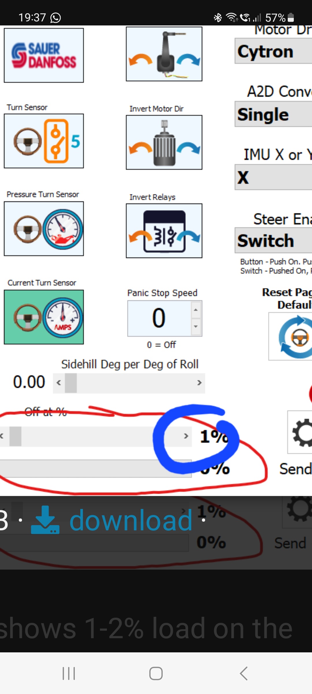
Also i see you have ‘switch’ selected for your steer enable, are you using a switch or momentary switch? If so i needs to be set to ‘button’ . I only ask as it caught me out once, i wss using a button but had switch selected so trying to overide the steering it was constantly try to re enable. I set to button and it cured it. Worth checking

It should have the latest version. Everything else is working fine, my screenshot was just for info on my desktop on simulation mode to show the bar.

Do I need to have jumper on red circle?

Not sure on them but don’t think so but pretty sure you’ll need some here

I have them on right and left but wondering if I need it also on remote/pressure for the current sensor to work.

Ive got the standard aio and just checked andi havnt got the jumpers where your indicating and mine works ok.
Also a screenshot of my jumpers

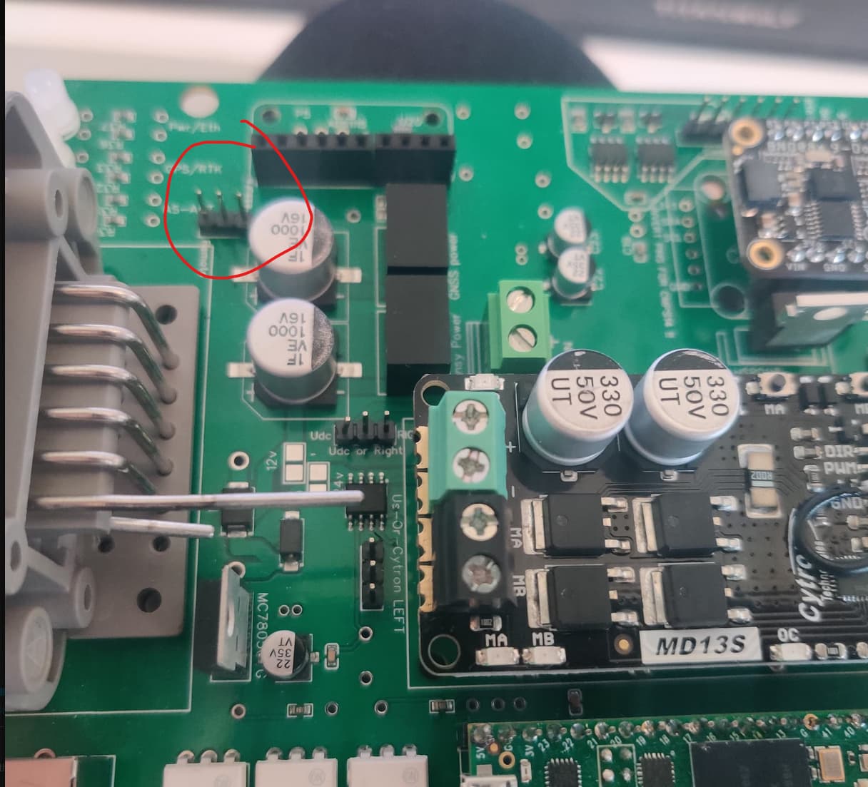
I just realised that I have powered my cytron directly from the pins. Does this mean that my current sensor is bypassed and that is why it doesn’t work?

Yes it probably does. Use the 24v in screw terminal to power the cytron

You need to solder the 12 or 24v pads, how is power getting to the Cytron?

Exactly. Are you using 24v?

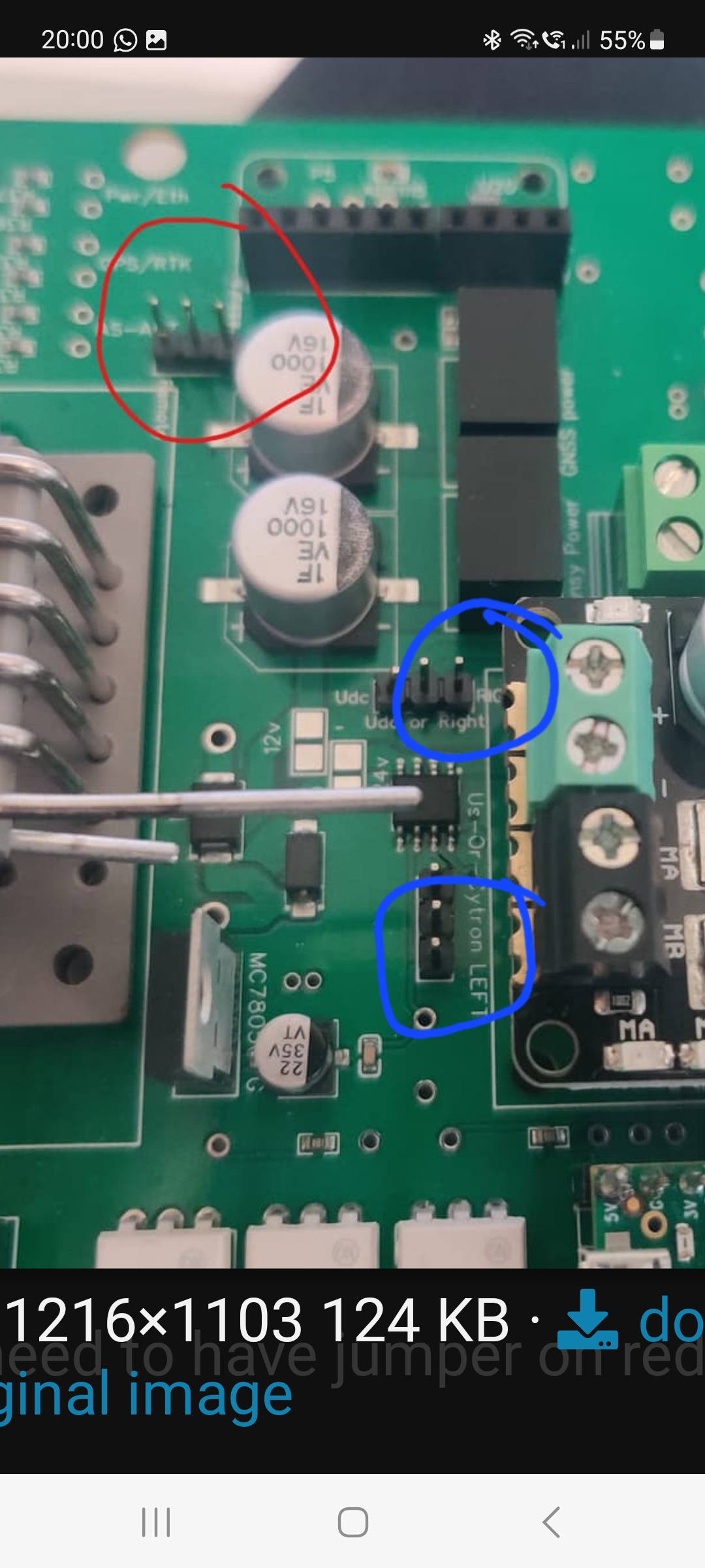
The bent pins you have showing i guessing there are direct to cytron? Remove that connection from the cytron and extend a wire from the pins to the 24v in terminal. Then you’ll need to solder the 24v pads as teddy said. This is if your using 24v motor

1 Like

I am running power from the bent bins directly to the cytron. I was afraid of burning my PCB because apparently power lines are thin on the first version of it. And I haven’t got definitive answer if they are capable of running Phidgets motor on 24v.

If your using the 24v motor your ok on the traces front, it was the 12v motors that drew too much power. I think @TeddyStamford put up a video of testing the amp draw on a 24v motor was was something like 3.2v draw at full turning.

Hi, I found such a picture here in the chat, do you think the wires of this length do not have a negative effect on BNO085?

Works well!

edit:
without soldering, you can use:
Flexible Qwiic Cable - Breadboard Jumper (4-pin) - PRT-17912 - SparkFun Electronics

1 Like

Thank you :+1:

Guys, I have questions, I don’t have 3.3v for BNO here:

3.3v is near “invert pins for cmps” writing, is that expected?

I want to try bno from aliexpress, but no voltage there:

3,3v is output from bno.
Depending the board, Vin is already 3,3v. Check with a multimeter

3.3 volt for bno comes from the teensy.

Its plugged in board… as Pat said Vin pin has 3.3v but 3v3 pin don’t and it shouldn’t okay… so I have to use wires for this IMU

Another question, its my first board… :stuck_out_tongue_closed_eyes:

I can use USB to Ethernet adapter and connect board to tablet no need for extra USB for f9p?