And about the motor, one goes to the pin 87 of the relay, and the other one stays on the plug 6 of the Ampseal ?
Thats it you got it. 2 wires going to the motor, 1 stays as it is and you’ll be chopping the other wire through fitting a relay in the middle. You’ll also be adding the lock pin wire and an earth wire to the relay ![]()
1 Like
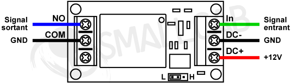
Ok, I’ve seen this post on the Github but I’ve bought an other one, but I think that will do, it’s also a 12V relay, and I have a “NO” and a “NC” plug, so I’ll take the “NO”.
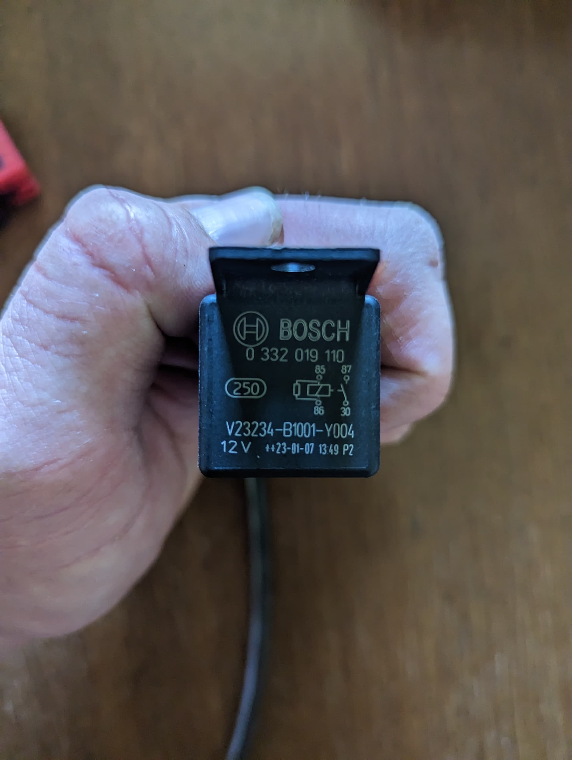
I’ll check the datasheet of the Bosch one.
Its the NO setup youll need
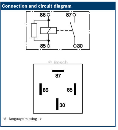
I’ve found the datasheet of the Bosch, but in my case, I’ve 5 wires to plug…
I found a wiring diagram on a french forum of AgOpenGPS.
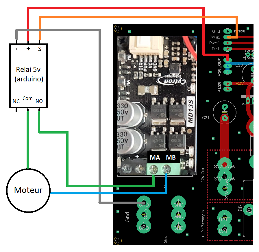
I think it’s something like a signal I need to “engage” the relay.
On the picture it’s a 5V relay, but mine it’s a 12V
You can use the LOCK pin on the ampseal connector to engage the relay and connect the other side of the coil to gnd. You should place the relay so it closes either the RIGHT or LEFT connection on the ampseal.
The LOCK pin goes high when steering is engaged and should have enough current to trigger a relay.
I’ll try it, an dI think in my case I have to plug 12V on the COM.
I’ll explore it tomorrow, and if it’s too complicated, I’ll buy the Bosch one.
Thank you to all of you ![]()
Is this the board your using?
On the standard aio pcb you only need to connect 4 wires to the relay and its all done externally. If you use the bosh NO relay and follow the guide it couldn’t be any easier and it works a treat
1 Like
I use the all in one PCB, the picture I post is on a French forum.
But I think that I’ve found a wiring diagram which will fit to my case.
This is for a 5V relay used with the old V2 PCB.
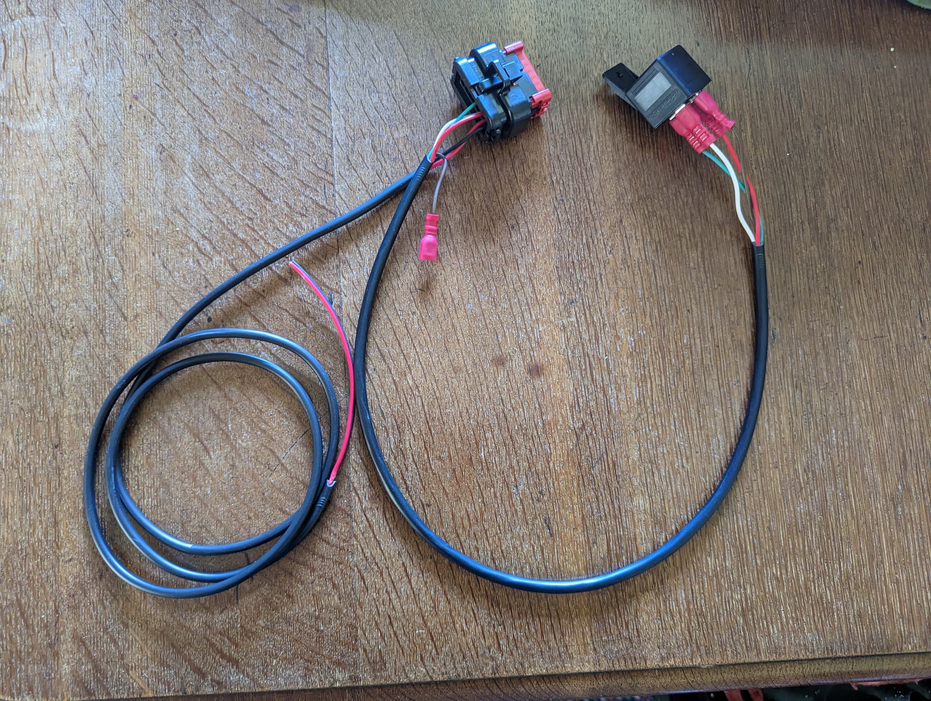
You need a 12V NO relay, It really is simple all you need to do is crimp some female 6.3mm spade connectors.
I will make a Relay with wire tails today, picture worth a thousand words.
1 Like
Mine is a 12V relay, the reference of the component on the plate is SRD-12VDC-SL.
Thank you for the future wiring ![]()
That relay is for a circuit board, it will have small pins.
You need a relay like this, you will find in your car…
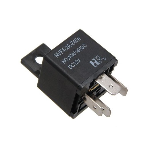
They are very cheap.
1 Like
Ok then I will buy this one, that will be easier ![]()
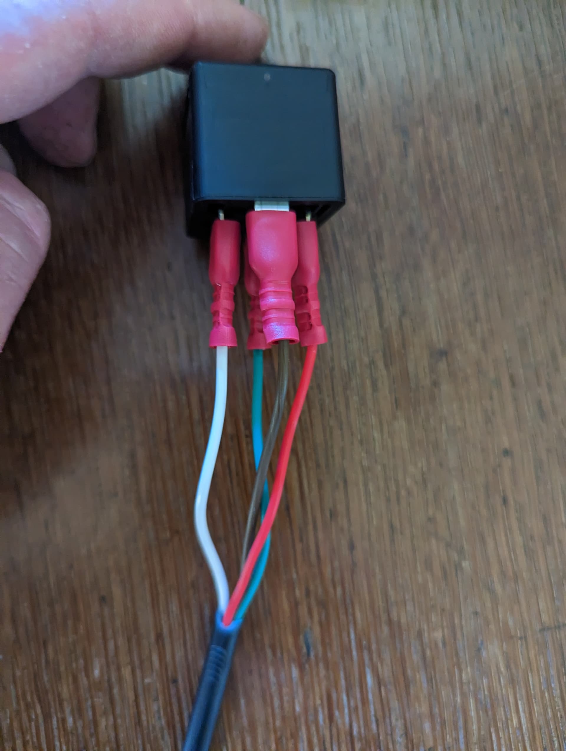
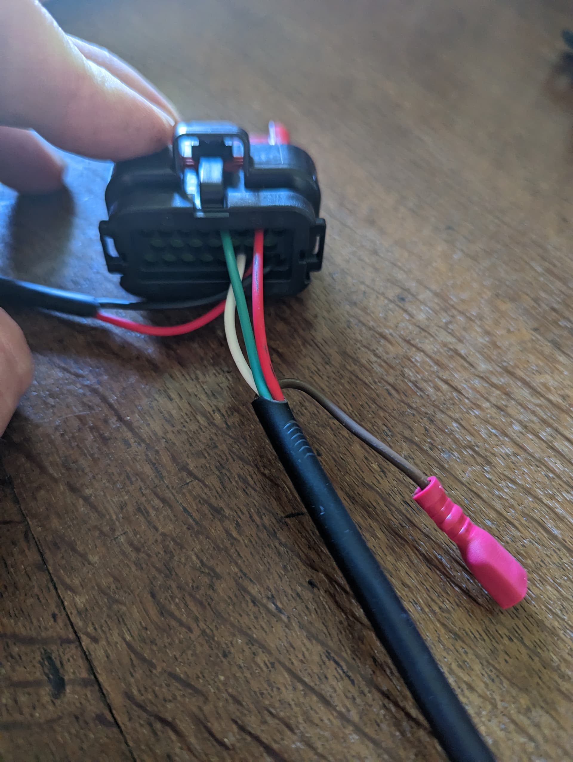
You can see an insualted female spade connecrtor with brown wire close to plug this connects to the Phidgets motor, the other wire from the motor connects to Pin 6.
Relay Pin 30: Pin 5 Ampseal
Relay Pin 85: Pin 7 Ampseal
Relay Pin 86: Pin 21 Ampseal
Relay Pin 87: Electric Motor left
3 Likes
I now have my autosteer working but I don’t know how to enable the current turn sensor. It should be on my 2.4 version board, right? When I put it on, it only shows 1-2% and doesn’t go up even when I try to force steering wheel against motor. It just burned my fuse. Is there something I need to do to get it working?
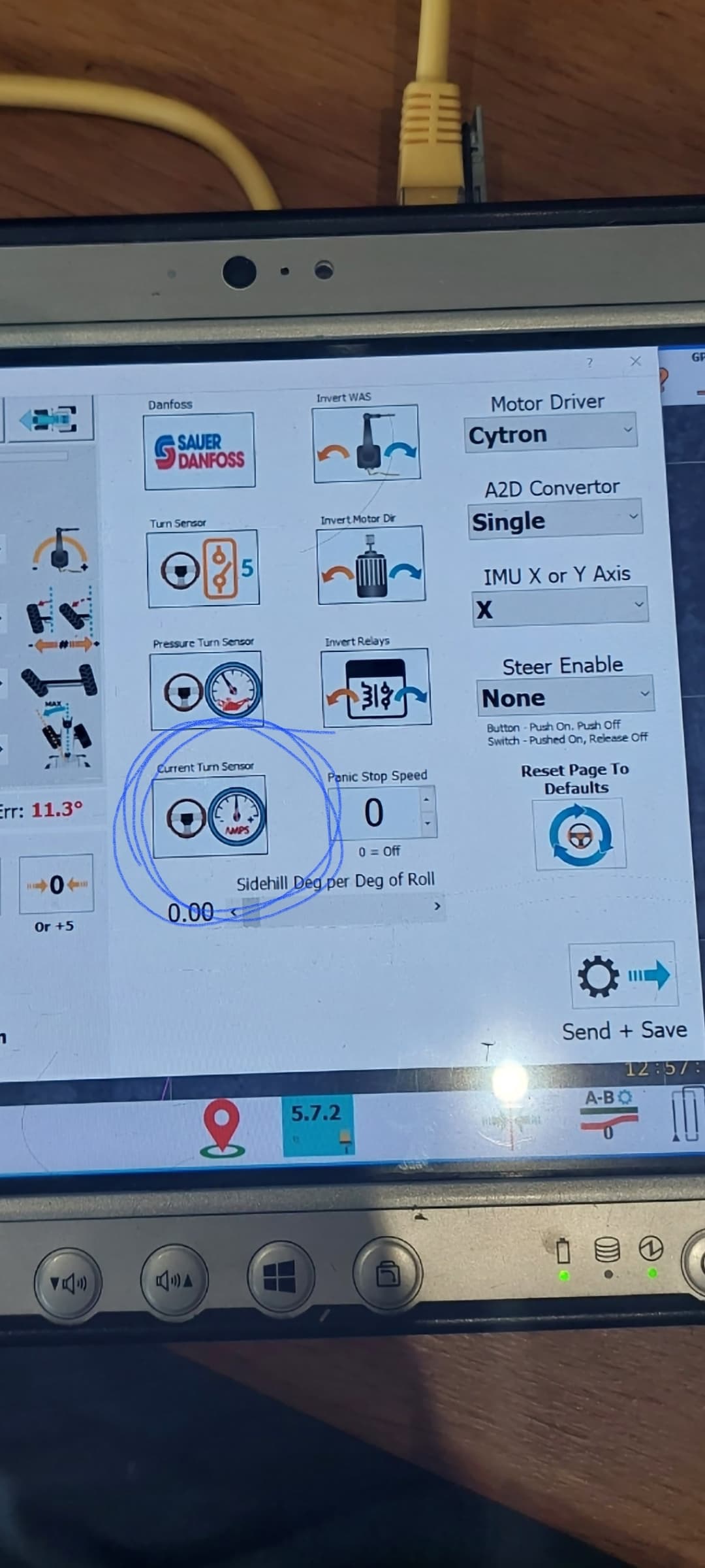
Click on this icon and you’ll then get another bar graph pop up. Set it at roughly 30 to start with and have another play about. Remember to save after everytime you change it.
Have mine set at i think 24, any lower and it seems to trip out a bit especially when preforming headland turning
1 Like
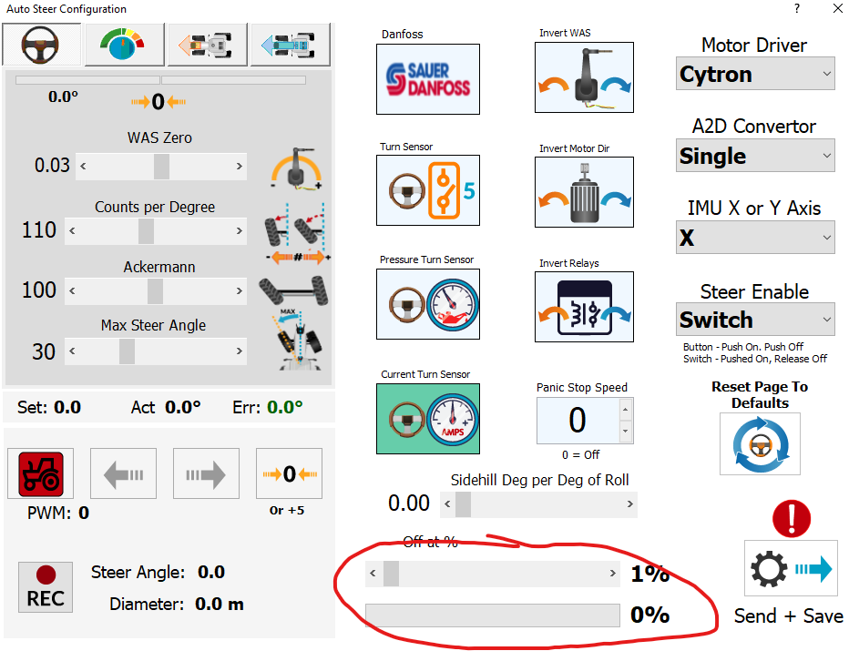
I tried that but it only shows 1-2% load on the bottom bar so nowhere near 30%. Do you need the jumper wire on the board on pressure pin or is it just for pressure sensor?
Are you using the latest firmware ino on the Teensy? There was a bug like that on an earlier version a few months back.
Try updating the Teensy.