hello, what firmware it´s better for single micro f9p 1.32 or 1.13 ? Actually i have 1.32 i´ll have any problems to downgrade?
thanks
for singles it doesn’t matter. Downgrading is not a problem. For Dual, 1.13 is recommended.
single system for those using rtk base station?
Hi everyone,
I have some questions about wiring before test with battery.
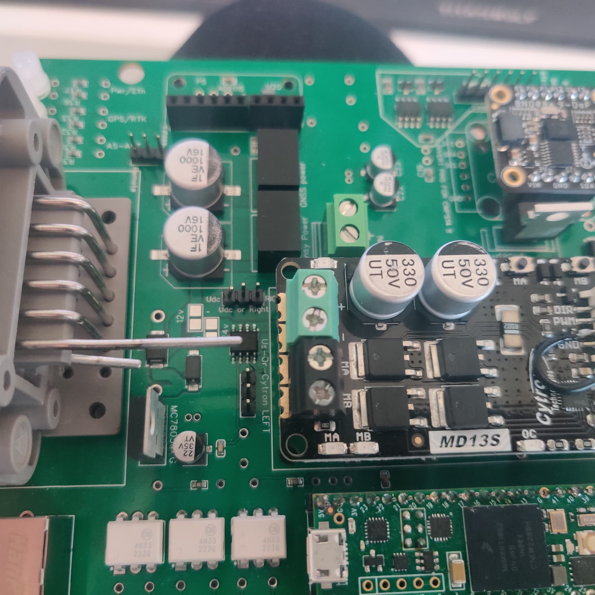
About the output of 24V converter, do I plug it direct on the Cytron (on + and - screw terminal), or do i plug it on the screw terminal marked “24V IN” ?
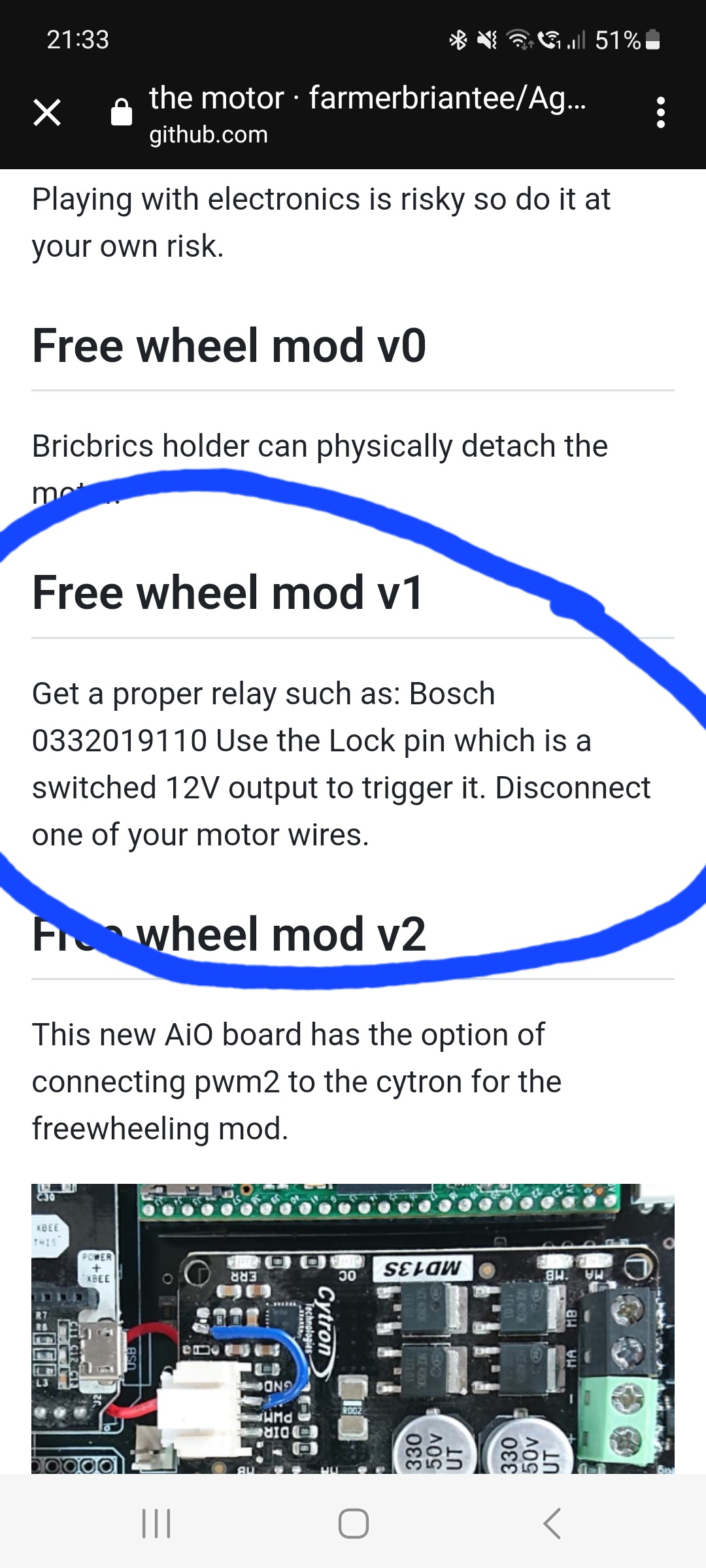
I’ve also planned to use a relay to “disconnect” the motor from the PCB when I don’t use it.
Regarding of what I’ve read, I think to wire lije this :
MA Cytron ->Motor +
MB Cytron → NO relay
COM Relay → Motor -
5V PCB → 5V relay
GND PCB → GND relay
PWM2 PCB → IN relay
Am I right ?
I also want to use a momentary button to engage the steering. The “output” of the button, I plug it to the pin 8 of the Ampseal, isn’t it ?
Thank you in advance !
For 24v to the cytron use the 24v in screw terminals. You will also need to solder the 24v pads infront of the cytron and add the 2 jumpers aswell.
For the relay mod its all done off the ampseal connection, nothing gets soldierd to the cytron for this mod, will find you a screen shot of the relay pinout. You will need an NO relay.
Steer switch you need a momentary push button. Connect 1 side of the switch to pin 8 on ampseal and the other side of the switch to ground.
Thank you very much!
That confirms what I was thinking.
So on the Cytron, there is nothing plugged in the +/- screw terminals ?
It’s very nice to have this advices instead of doing mistakes!!
I have nothing going to the screw terminals on the cytron my aio pcb.
Theres a number for the correct relay you need on the github
Dont forget you’ll need to solder the 24v pads and add some jumpers
Ok thanks!
For the jumpers and the 24V pads, it’s already done ![]()
I have the first version of this all in one pcb. I am going to use Phidget motor with 24v. Should I solder extra wires for the power connections or are the pcb traces enough? I have seen some comments that traces aren’t thick enough and some that they are fine.
24v will probably drain less current than 12v motor which means thinner wires can be used(or pcb traces)
P(W) = U(V) * I (A)
1 Like
I am now assembling my PCB, I have bent two pins from my Deutsch connector to use them to power 24v to Cytron. Can I just wire pins directly to Cytron or should I use the 24v connector that is on the board?
1 Like
Can chinese BNO08X be used instead of adafruit BNO085 on all in one boards since I already have one from Aliexpress?
On PCBV2 I used jumper wires and glue to connect the BNO08x module. The same technique could be applied to Aio boards.
1 Like
One more question about the freewheel mod with a relay.
When there is a relay, do I need to unsolder the pin of the Ampseal connector from the PCB to connect direct on the COM port of relay, or can I let it soldered to the PCB meanwhile I connect it to the COM port of the relay ? I think that I’ve to unsoldered but all the pins are soldered and I think that I have to unsolder all to get mine ![]()
Not sure what you mean exactly but you don’t need to modify or unsolder anything on the pcb. Leave the ampseal soldered to the pcb like it should be and the relay sits outside the pcb and you connect to the pins/wires going into the ampseal from the outside and use the pins as shown in the previous picture
What I’m saying is that without relay, when we connect the wires on the Ampseal connector on the pins 5 and 6, we have the output of the Cytron I think, no?
So if we use a relay, we have to connect one side of the motor to the Cytron (via the Ampseal connector), and the other one to the relay, which is connected to the Cytron. So what I mean is, if I let the original wiring and add the relay, I will be sending two “information” to the motor.
But maybe I’m wrong.
The relay mod is completely external to the pcb and is instead on the wiring harness. You do not interrupt any connections to the cytron.
1 Like
Your overthinking it ![]()
Don’t make any alterations to the cytron or the pcb.
On the outside of the pcb fit a relay anywhere in the cab out of sight and wire up as the screen shot.
1 Like
That will be too much easy if not ![]()
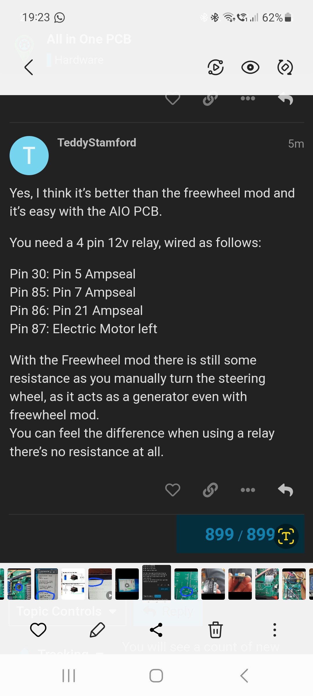
Ok, I’ll plug it like the screenshot, but what is 30, 85,86 and 87 on the relay ?
30 : COM of the relay ?
85 : IN of the relay ?
86 : GND of the relay ?
87 : NO of the relay ?
the relay you need its a NO relay. Cant remember the number of the relay but if you look on the github under freewheel mods it tell ls you model of relay you need.
Numbers 85 86 87 30 are printed on the relay next to the pins. Use these numbers to connect to the corresponding pins on the ampseal wiring in the screenshot