Correct. No extra cables needed.
1 Like
Do I need to make any changes to .ino for connecting this way?
I uploaded TeensyModules>V2.5>Firmware>Autosteer_gps_teensy_v2_5>Autosteer.ino
No changes as far as I know
1 Like
Anyone select 2oz copper option for outer and inner layers? I know it costs more but will there be fab issues if traces are too close with a 2oz board?
Looks like 13 parts are not available when I uploaded the standard ampseal board. I might just order parts from DigiKey and build it all by hand. Soldering SMT parts isn’t an issue for me. Have boom microscope, Metcal iron, and a hot air pencil.
I followed Ethernet setup on GitHub wiki page. Over UDP Imu and auto steer is green but antenna is not. Over USB to f9p receiver antenna is green so it works… Whats my problem? ![]()
I got green Ethernet led on pcb but no led active for GPS…

GOT IT… Receiver had wrong configuration file haha
Will this box still fit the newer release of the v4.1 standard pcb or have any dimensions changed? If not are there any other .Stl files someone has out there for an enclosure for a standard v4.1 pcb?
I think nothing changed, but let me check
It fits nicely, I was able to swap v2.5 STD boards with v4.1 STD (so we got the 20A ampmeter ![]() )
)
With double thick copper it handles well the 12V motors.
1 Like
I usually go with double copper. Not sure if it’s necessary but we use 12V motors, which means double Amps that go through the board so it’s the least we can do.
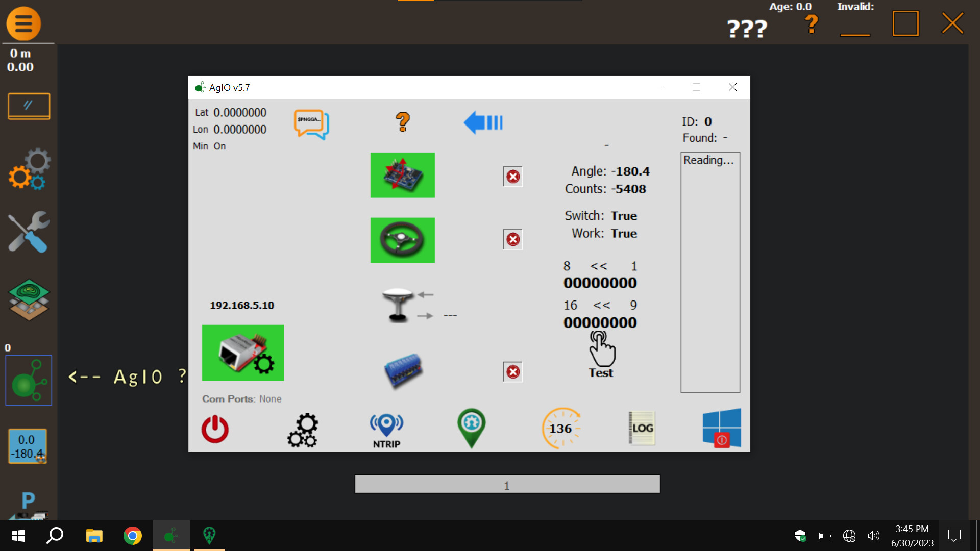
Hello, I have a question. What is connected to the all in one board so that there is a Com port here, because I have none?
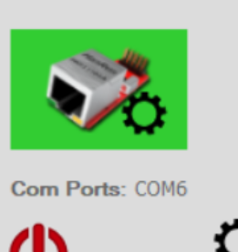
Could you please attach a pic about the proper configuration with the BNO from Ali? Thanks!
1 Like
I used 90 deg bent pins and stick it in… but to remain proper order I had to extend one pin to make it longer so it can get into right place… and fixed it with a zip tie so it doesn’t wiggle
I have steer ready tractor and All In One 2.4. It works, but there is something wrong with the tractor WAS. I would like to try a different WAS and connect it directly to the AIO. Is it possible and what code should be used?
Typically the AiO is used with it’s own WAS, connect to WAS_5V, WAS_H and gnd. The main/official code works.
I made my own separate program for testing was with arduino, when I didn’t have AIO Board yet. I can share it if you want…you can determine if its actual WAS or AIO board not reading data problem…
With “Autosteer_gps_teensy_v5.ino” Honeywell WAS works, but steering does not work with canbus.
With Tony’s modified code, everything works, but the WAS signal on the tractor is unstable. The repairman has also determined with the service tool that there is something wrong with the tractor’s WAS system. So I can’t get a straight line.
How is it possible to use Honeywell WAS directly to the AIO and steer with canbus?
What were the configuration settings that you changed to make it work? I am currently having a similar issue.
2SC2884 LCSC Part # C24205
KSP2222ATA
I am having difficulty finding the two Transistors I sent. Is there an alternative Transistor?